Shifter with park lock and neutral lock device

a technology of neutral lock and shifter, which is applied in the direction of mechanical control device, manual control with single controlling member, instruments, etc., can solve the problems of reducing the efficiency of manufacture while, adding to storage costs, and modern vehicle shifters also have another problem

Inactive Publication Date: 2001-12-04
GRAND HAVEN STAMPED PRODS DIV OF JSJ
View PDF8 Cites 70 Cited by
  • Summary
  • Abstract
  • Description
  • Claims
  • Application Information

AI Technical Summary

Benefits of technology

In another aspect of the present invention, a shifter for shifting a vehicle transmission between a plurality of gear positions includes a base having notches corresponding to the gear positions and a shift lever pivoted to the base for movement along a first path between the gear positions and pivoted for movement into and along a second path that extends parallel the first path. The shift lever is adapted to shift the transmission in a first manner when in the first path and to shift the transmission in a second manner when in the second path. The shift lever includes a pawl operably engaging the notches to control movement of the shift lever between the gear positions. A releasing member attached to the base is configured to engage and retract the pawl of the shift lever, causing the pawl to disengage the notches when the shift lever is moved to the second path.
In another aspect of the present invention, a shifter for shifting a transmission between park, reverse, neutral, and drive gear positions includes a base, a shift lever pivoted to the base for movement between the park, reverse, neutral and park gear positions, a control circuit adapted to sense vehicle conditions, and an electromechanical device on one of the base and the shift lever that is connected to the control circuit. The electromechanical device is configured to both lock the shift lever in the park gear position when a first set of vehicle conditions are met, and also to block the shift lever from moving from the neutral gear position until a second set of vehicle conditions are met.
In yet another aspect of the present invention, a method includes providing a shifter having a base and a shift lever on the base movable between a plurality of gear positions including a park position, a reverse position, and a neutral position, and includes providing a solenoid on one of the base and the shift lever. The method further includes operating the solenoid to lock the shift lever in the park position until first predetermined vehicle conditions are met, and later operating the solenoid to unlock the shift lever to allow the shift lever to move from the park position. The method still further includes, in a separate step after the shift lever has been moved from the park position, operating the solenoid to prevent the shift lever from moving from the neutral position until second predetermined vehicle conditions are met.

Problems solved by technology

This can cause numerous problems in factories created to manufacture both left-hand drive and right-hand drive vehicles.
Further, twice as many tools and fixtures must be created and lower volumes of each parts are used, thus reducing efficiencies of manufacture while adding to storage costs.
Modern vehicle shifters also have another problem.
Some shifter systems are proposed that are constructed to prevent a transmission from shifting from drive gear position into reverse gear position while the vehicle is going too fast, but they typically do not prevent the shift lever itself from being accidentally moved into the reverse gear position.
This can result in a potentially unsafe condition since the vehicle suddenly and unexpectedly operate.
As a result, a shift lever cannot be moved out of its park gear position until the predetermined vehicle conditions are met.
A problem is that solenoids are expensive, and including two solenoids in a shifter results in a relatively expensive shifter assembly.
However, cables are also expensive to purchase.
Further, the cables must be routed in the vehicle and connected at each end, making them expensive to install.
Further, it is not at all clear how such a construction could be made to provide a neutral lock function.

Method used


Image

  • Shifter with park lock and neutral lock device
  • Shifter with park lock and neutral lock device
  • Shifter with park lock and neutral lock device

Examples


Embodiment Construction

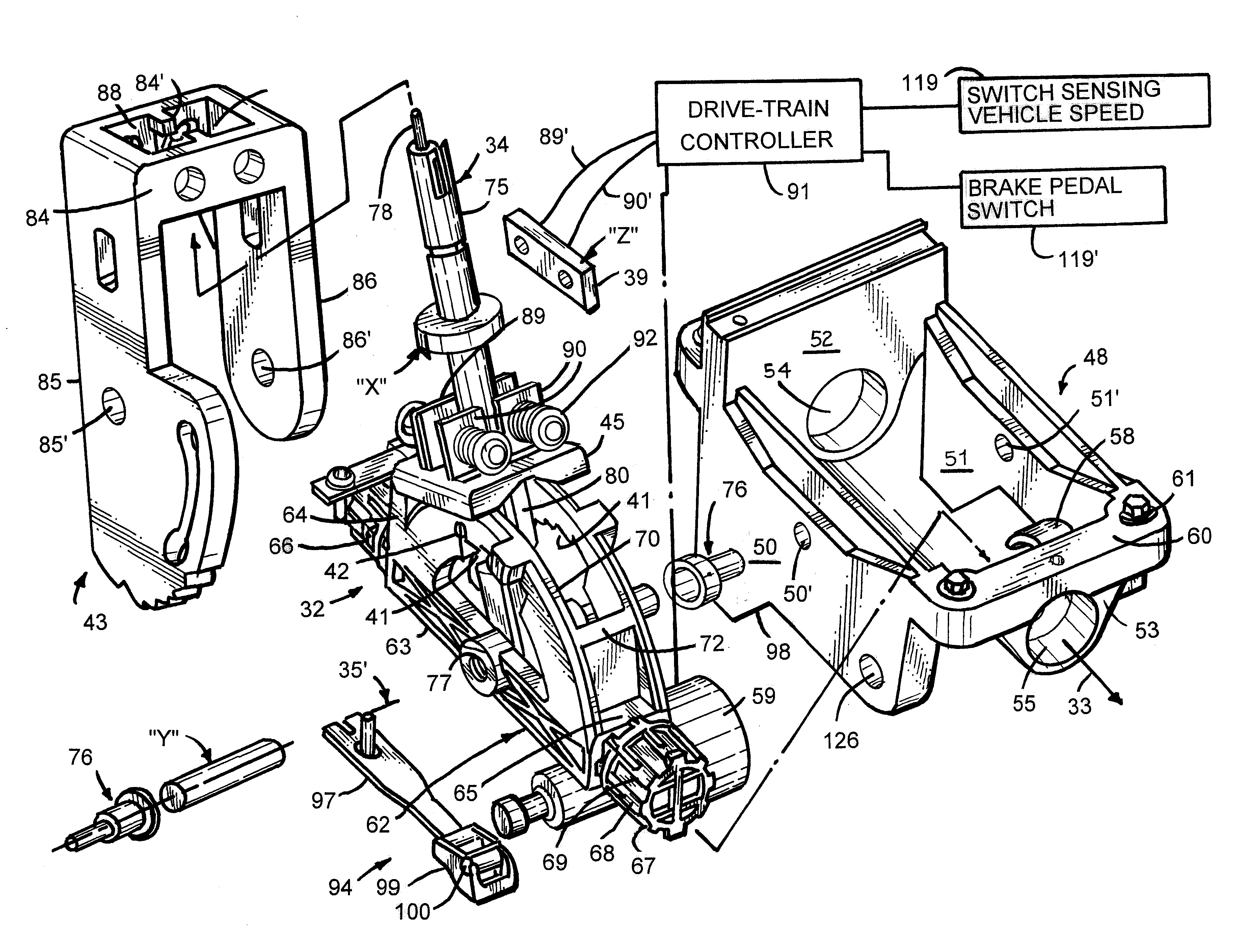
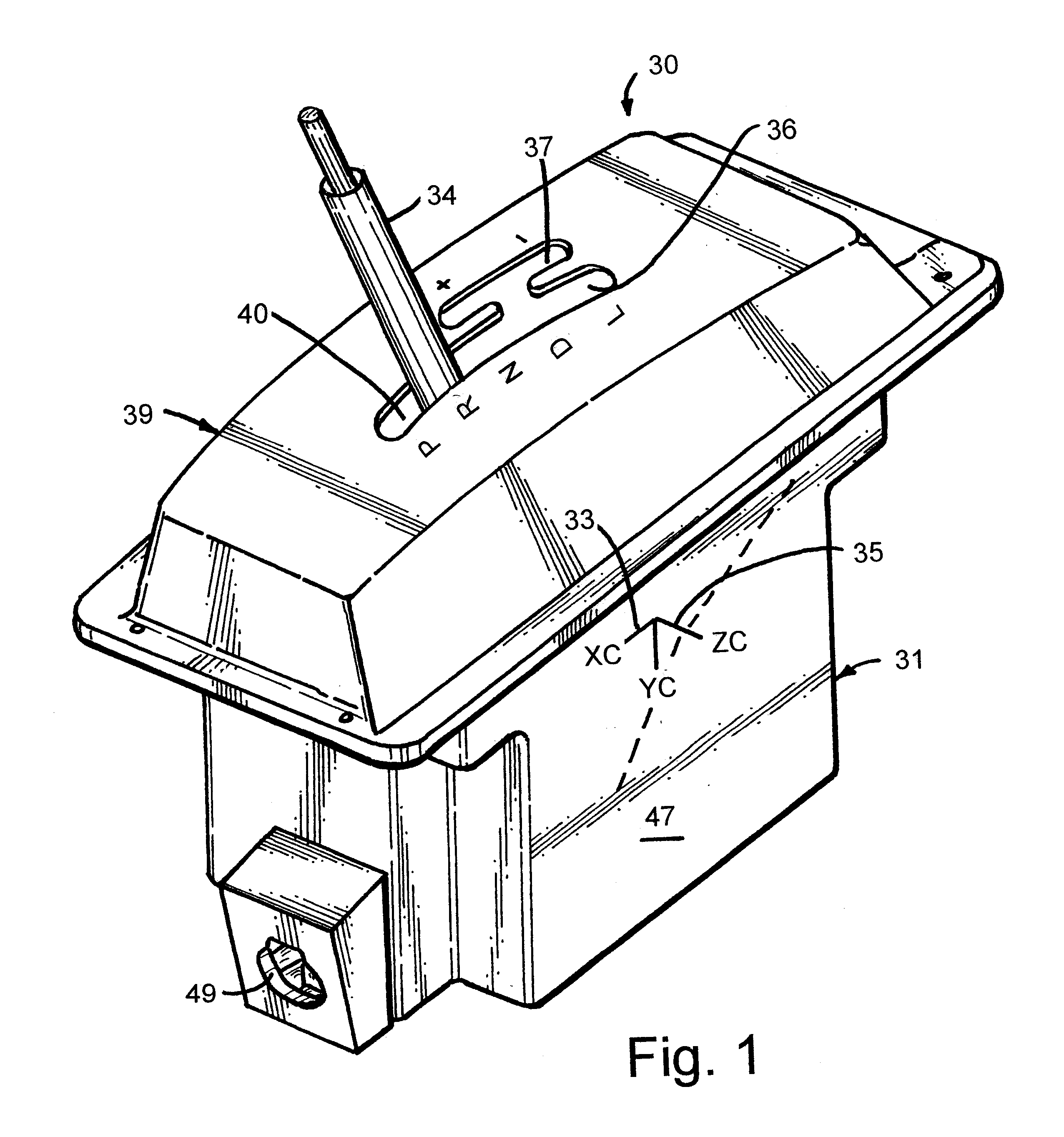
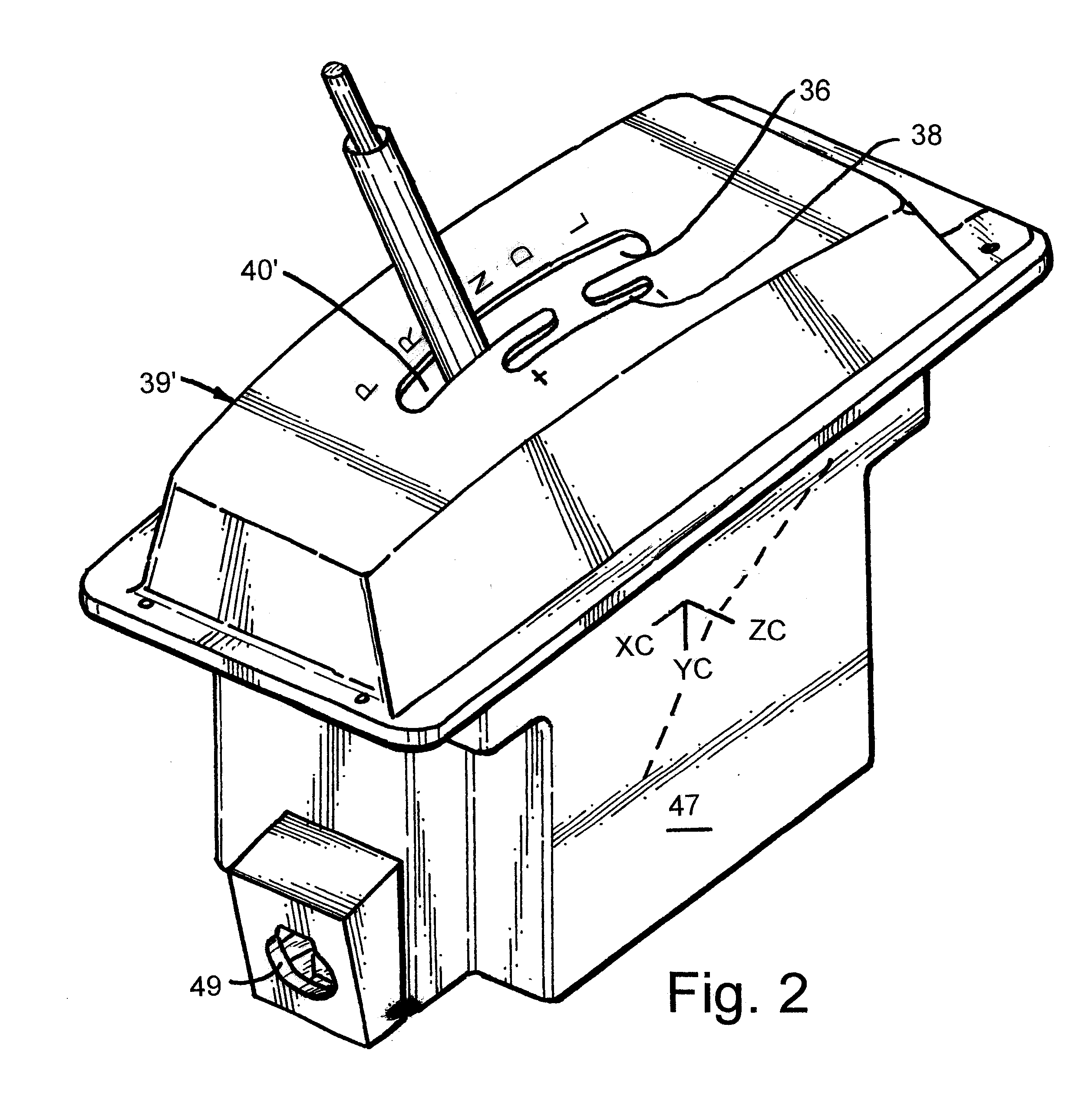
A shifter 30 (FIG. 1) embodying the present invention is provided for shifting a vehicle transmission. The shifter 30 has a shift lever 34 that is movable along a first path 36 in an automatic shifting mode that includes the automatically shifting gear positions park "P", reverse "R", neutral "N", drive "D", and low drive "L" (PRNDL), and that is movable along parallel second or third shift paths 37 and 38 in a manual shifting mode including upshift and downshift gear positions ("+" and "-"). Specifically, the shifter 30 includes a base 31 and a lever carrier 32 (FIG. 4) pivoted to inner casing 48 of the base 31 (FIG. 4) for movement about a first axis 33. The shift lever 34 is pivoted to the lever carrier 32 for movement about a second axis 35 perpendicular to the first axis 33. By this arrangement, the shift lever 34 can be selectively pivoted along the center or first path 36 (FIG. 3) or selectively moved into and pivoted along the parallel second and third paths 37 and 38 locate...


PUM


Abstract

A shifter is provided for shifting a vehicle transmission between an automatic shifting mode that includes the automatically shifting gear positions of park, reverse, neutral, drive, and low drive, and a manual-shifting mode including upshift and downshift gear positions. The shifter includes a base, a lever carrier pivoted to the base for movement along a center shift path and side shift paths, and a shift lever pivoted to the lever carrier for movement between the different shift paths. The lever carrier has notches corresponding to the gear positions, and the shift lever has a pawl operably engaging the notches to control movement of the shift lever between the automatically shifting gear positions on the center shift path. The pawl is disengaged when the shift lever is moved into the side-located shift paths.

Description

The present invention relates to shifters for transmissions of passenger vehicles, and more particularly relates to shifters having devices to control movement of the shift lever between gear positions.Passenger vehicles in the United States have the driver's seat positioned in a front left side of the passenger compartment. The transmission shifter is typically positioned between the front vehicle seats for operation with the driver's right hand. However, passenger vehicles in many other countries, such as Japan, position the driver on the front right side of the passenger compartment. The shifter is often still positioned between the vehicle seats, but the shifter is located on a left side of the driver for left-handed operation. This can cause numerous problems in factories created to manufacture both left-hand drive and right-hand drive vehicles. For example, twice as many part numbers are created, one set for right-hand driven vehicles and one set for left-hand driven vehicles....

Claims


Application Information

Patent Timeline
Patent Type & Authority Patents(United States)
IPC IPC(8): F16H61/22F16H59/02B60K20/04
CPCF16H59/0204F16H61/22B60K20/04F16H2059/026Y10T74/2011F16H2061/223F16H2059/0239Y10T74/20067F16H2059/0273
Inventor BEATTIE, DALE A.BROCK, ROBERT D.DEJONGE, ROBERT A.
Owner GRAND HAVEN STAMPED PRODS DIV OF JSJ
Why Eureka
Try Eureka