
System and method for graphically manipulating display elements in a computer-based system

a computer-based system and graphic manipulation technology, applied in the field of computer-based ystems, can solve problems such as inability to intuitively manipula

Inactive Publication Date: 2001-12-04
AGILENT TECH INC
View PDF8 Cites 24 Cited by
  • Summary
  • Abstract
  • Description
  • Claims
  • Application Information

AI Technical Summary

Problems solved by technology

Oftentimes, such systems are not intuitive, causing the user to make multiple attempts to place a selected display element in a desired location.

Method used


Image

  • System and method for graphically manipulating display elements in a computer-based system
  • System and method for graphically manipulating display elements in a computer-based system
  • System and method for graphically manipulating display elements in a computer-based system

Examples


Embodiment Construction

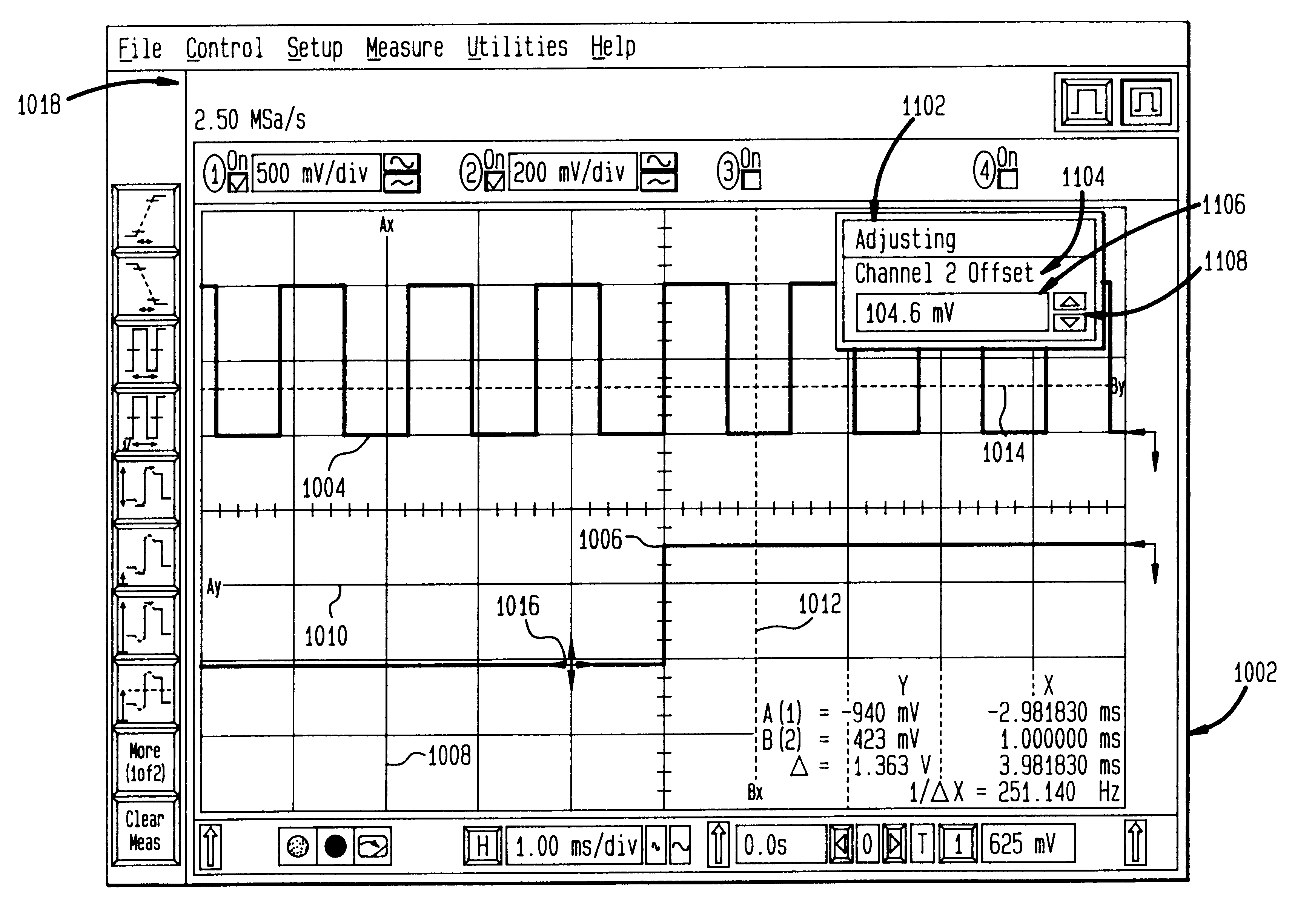
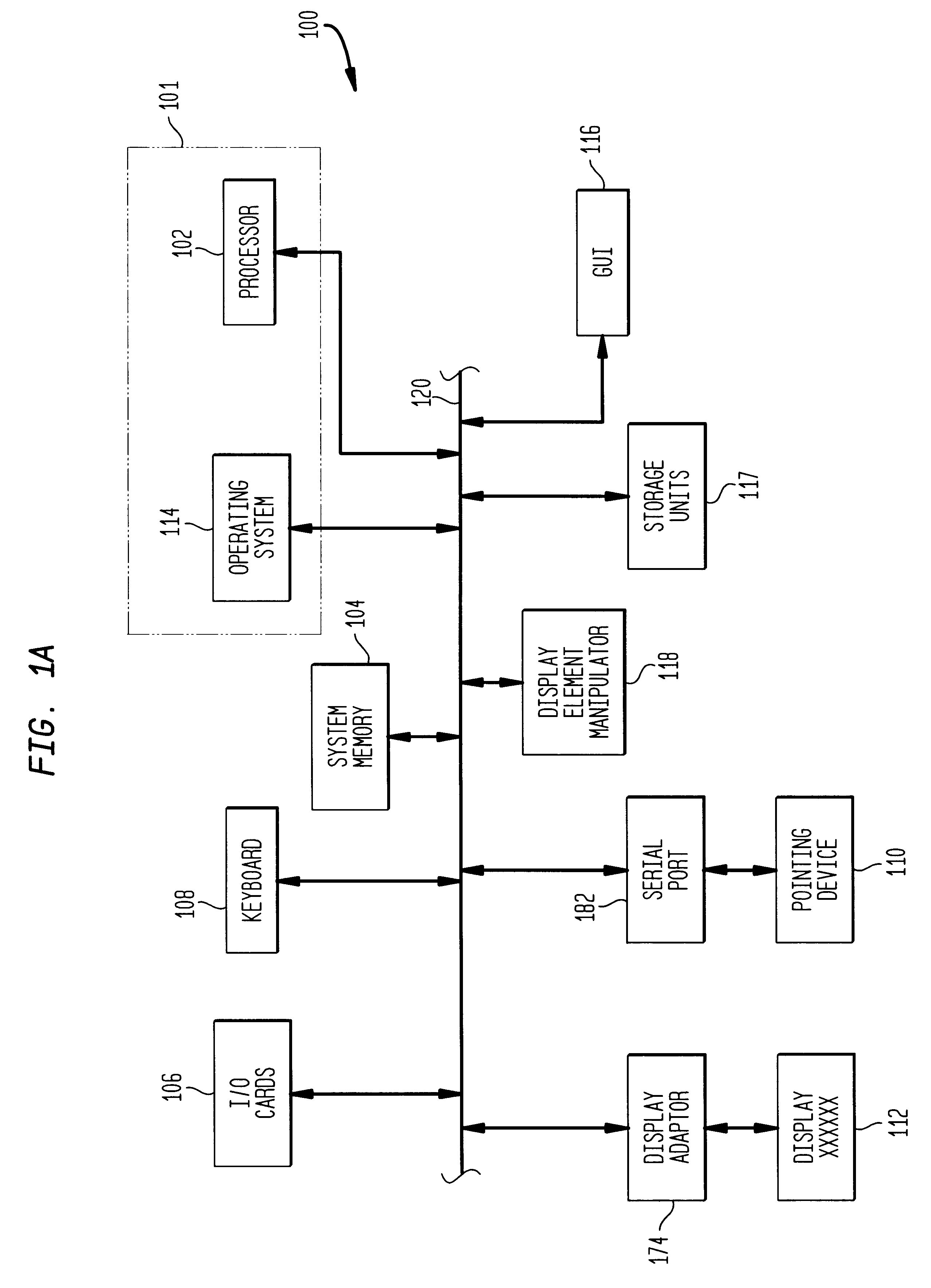
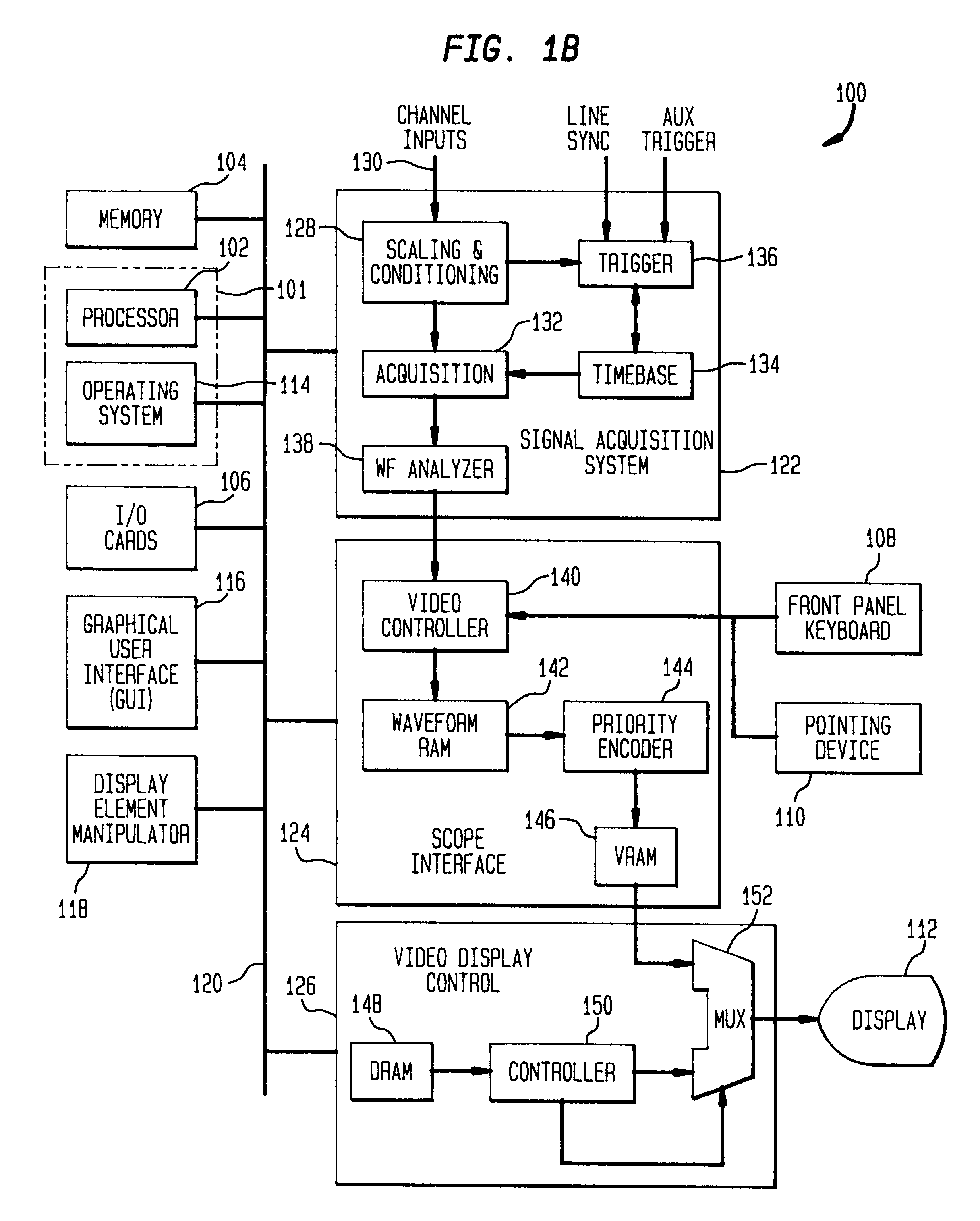
The present invention is a display element manipulation system and method that may be implemented in a computer-based system operatively coupled to a display device. Although any computer-based system may incorporate the present invention, the present disclosure is directed to a computer-based signal measurement system having a graphical user interface. In one embodiment of the present invention, the present invention is implemented in a test and measurement instrument such as a digital or analog oscilloscope, logic analyzer, network analyzer, spectrum analyzer or waveform generator. FIG. 1A is a functional block diagram of an exemplary computer-based system while FIG. 1B is a functional block diagram of an exemplary digital oscilloscope suitable for implementing the display element manipulation system and method of the present invention.

FIG. 1A is a functional block diagram of an exemplary computer-based system also suitable for implementing the present invention. Computer system 1...


PUM


Abstract

A display element manipulation system and methodology for use in a computer-based system for providing a user with the ability to graphically manipulate a selected positionable display element presented on a display device. The display element manipulation system includes a display element selector configured to determine permissible adjustment directions for a selected positionable display element. The display element manipulation system also includes a display element position determinator configured to determine an adjustment command representing a desired adjustment direction and position for the selected display element.

Description

BACKGROUND OF THE INVENTION1. Field of the InventionThe present invention relates generally to computer-based ystems and, more particularly, to graphically manipulating display elements in a computer-based system.2. Related ArtA common technique for presenting information to users of computer-based systems is through use of a graphical user interface (GUI). A graphical user interface is typically part of an environment provided by an operating system executed by a processor in the computer system. Generally, the GUI is controlled by the operating system in response to commands provided by a user and application programs or other processes executing on or accessible to the computer-based system.Common to virtually all conventional GUIs is the use of a mouse or other pointing device in a windowed environment. Windows are rectangular areas presented on a display that contain textual and / or graphical information related to the operation of the application program, operating system or ot...

Claims


Application Information

Patent Timeline
Patent Type & Authority Patents(United States)
IPC IPC(8): G01R13/20G06F15/00
CPCG01R13/20G06F15/00Y10S715/97G06F3/0481G06F3/04847
Inventor ALEXANDER, JAY A
Owner AGILENT TECH INC
Learn More