Techniques for reading two dimensional code, including MaxiCode

a two-dimensional code and code technology, applied in the field of two-dimensional code reading, can solve the problem of image being rejected as showing too much til

Inactive Publication Date: 2002-01-22
SYMBOL TECH LLC
View PDF6 Cites 84 Cited by
  • Summary
  • Abstract
  • Description
  • Claims
  • Application Information

AI Technical Summary

Problems solved by technology

If this ratio is not met, the image may be rejected as exhibiting too great a tilt.

Method used


Image

  • Techniques for reading two dimensional code, including MaxiCode
  • Techniques for reading two dimensional code, including MaxiCode
  • Techniques for reading two dimensional code, including MaxiCode

Examples


Embodiment Construction

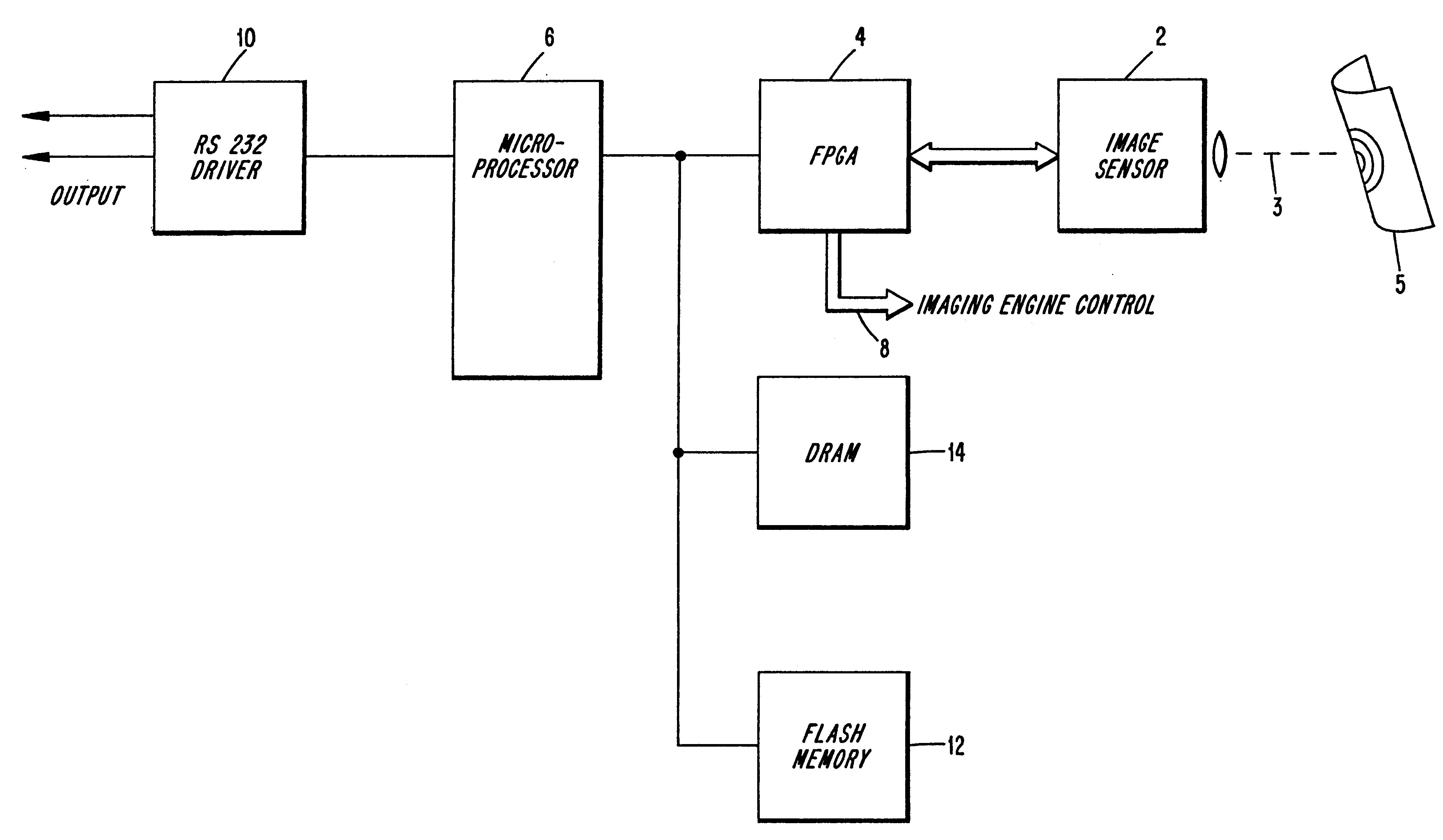
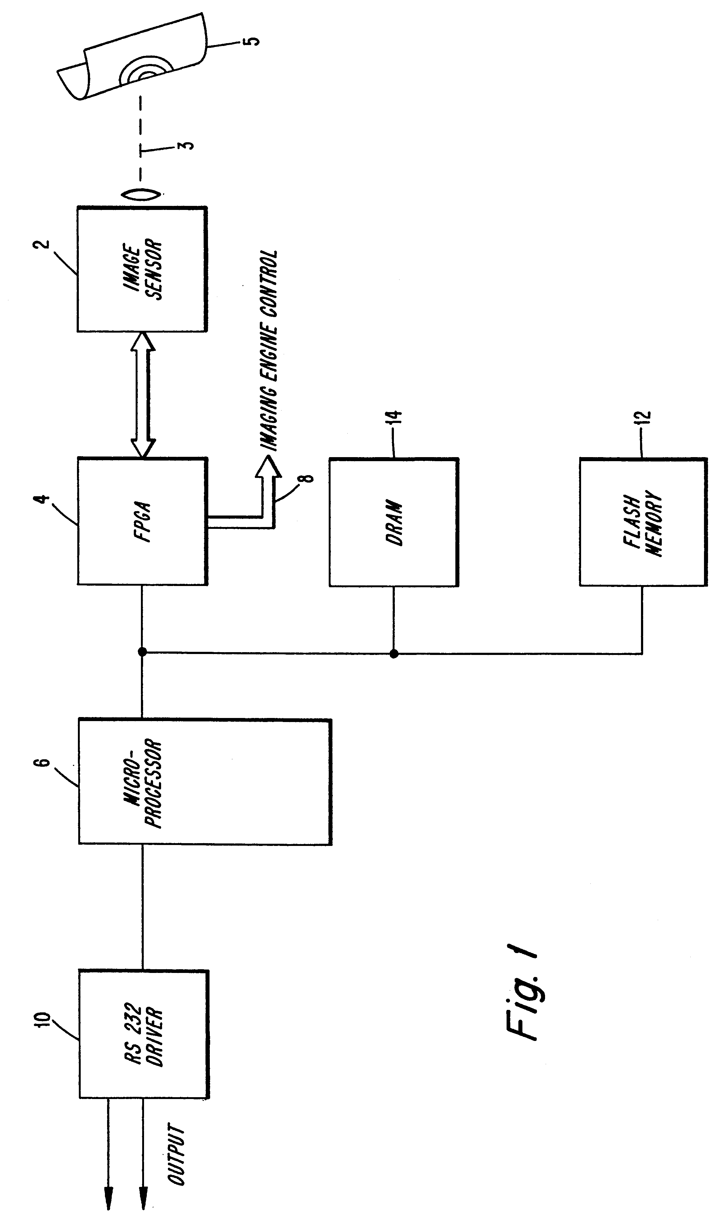
FIG. 1 is a block diagram of various electronic circuits employed in preferred embodiments of the present invention. An image sensor 2 has an optical axis 3. An image is obtained of a symbol, shown located on an arbitrary warped and tilted surface 5 (not in a plane and not perpendicular to the optical axis 3).

As shown in FIG. 1, electronic signals from the image sensor 2 pass to FPGA (or ASIC) circuit 4. In a preferred embodiment, the image sensor 2 includes a CCD detector and various signal conditioning circuits which produce a digital output signal. This digital output signal may be in the form of electronic signals corresponding to a two dimensional array of pixel information for a target field of view. Digital signals from the imaging sensor are supplied to the microprocessor 6 by the FPGA circuit 4. As indicated by the data line 8, the FPGA also provides control signals from the microprocessor for control of, for example, the aiming systems, illumination systems and objective l...


PUM


Abstract

The disclosure relates to techniques for determining the presence, orientation and location of features in an image of a two dimensional optical code. The techniques are adapted for use in mapping data in an image pixel plane with grid locations in a grid-based two dimensional code to account for size, rotation, tilt, warping and distortion of the code symbol. Where such a code is a MaxiCode, techniques are disclosed for determining the presence and location of the MaxiCode bulls-eye, orientation modules, primary data modules and secondary data modules.

Description

FIELD OF THE INVENTIONThe invention relates to techniques for reading two dimensional code such as MaxiCode. Aspects of the invention are particularly useful in imaging optical code readers which are designed to read various kinds of optical code.BACKGROUND OF THE INVENTION AND OBJECTSOptical codes are patterns made up of image areas having different light reflective or light emissive properties, which are typically assembled in accordance with a priori rules. The term "bar code" is sometimes used to describe certain kinds of optical codes. The optical properties and patterns of optical codes are selected to distinguish them in appearance from the background environments in which they are used. Devices for identifying or extracting data from optical codes are sometimes referred to as "optical code readers" of which bar code scanners are one type. Optical code readers are used in both fixed or portable installations in many diverse environments such as in stores for check-out service...

Claims


Application Information

Patent Timeline
Patent Type & Authority Patents(United States)
IPC IPC(8): G06K7/14
CPCG06K7/14G06K7/1443G06K7/1456
Inventor HE, DUANFENGHUNTER, KEVINJOSEPH, EUGENE
Owner SYMBOL TECH LLC
Why Eureka
Try Eureka