Piston pump

a technology of piston pump and piston pump, which is applied in the direction of piston pump, positive displacement liquid engine, liquid fuel engine, etc., can solve the problems of pressure surge and pressure pulsation of brake fluid, and achieve the effect of quick and economical manufactur

Inactive Publication Date: 2002-01-29
ROBERT BOSCH GMBH
View PDF14 Cites 41 Cited by
  • Summary
  • Abstract
  • Description
  • Claims
  • Application Information

AI Technical Summary

Benefits of technology

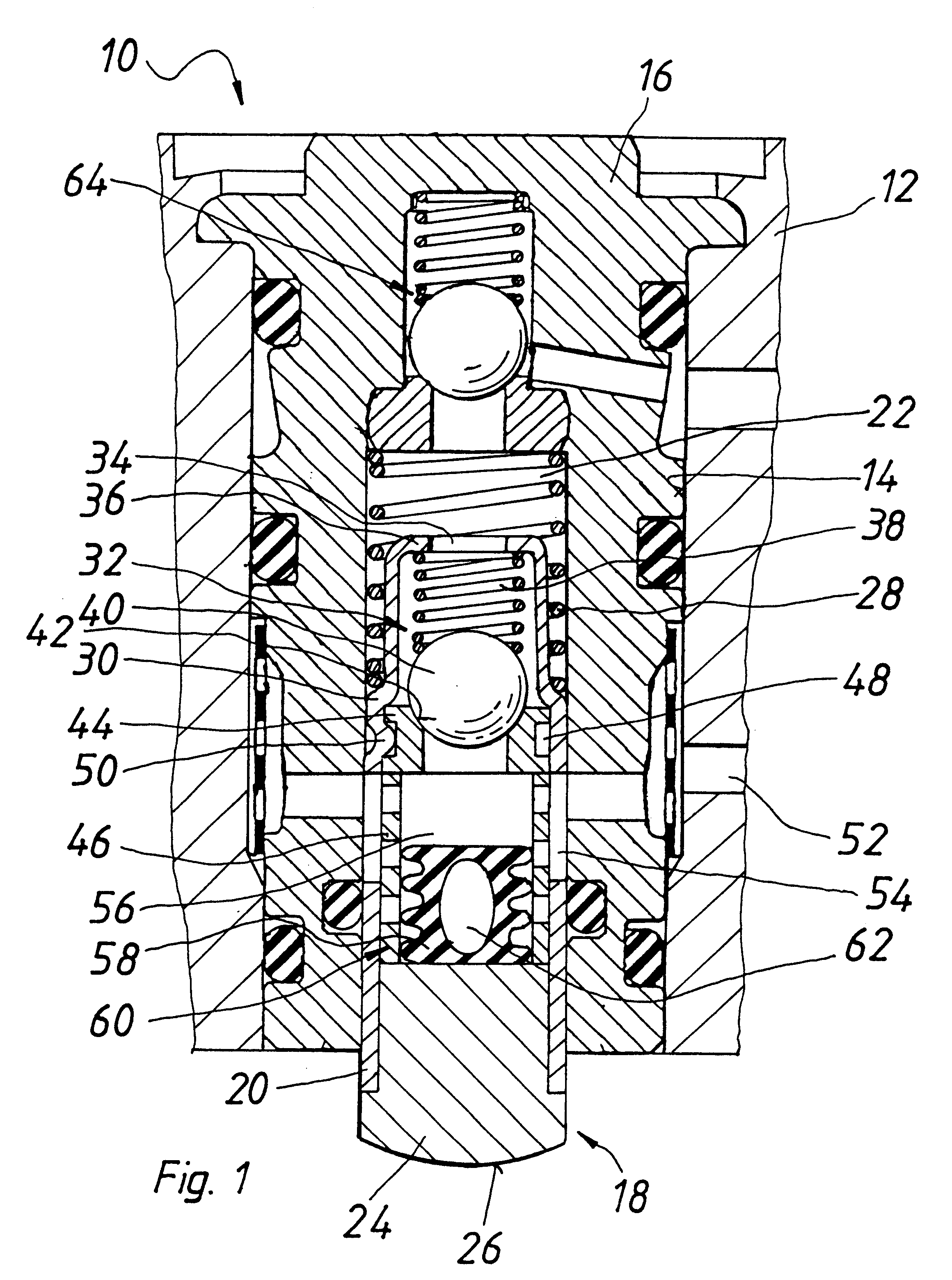
The piston of the piston pump according to the invention has a sleeve or a plurality of sleeves that form a circumferential piston wall. This sleeve may be produced by reshaping a piece of pipe, for instance. The piston of the piston pump according to the invention can as a result be manufactured quickly and economically.

Problems solved by technology

This interior damps pressure pulsations and pressure surges in the brake fluid, which in operation are brought about by the piston pump because of its discontinuous pumping mode.

Method used


Image

  • Piston pump
  • Piston pump
  • Piston pump

Examples


Embodiment Construction

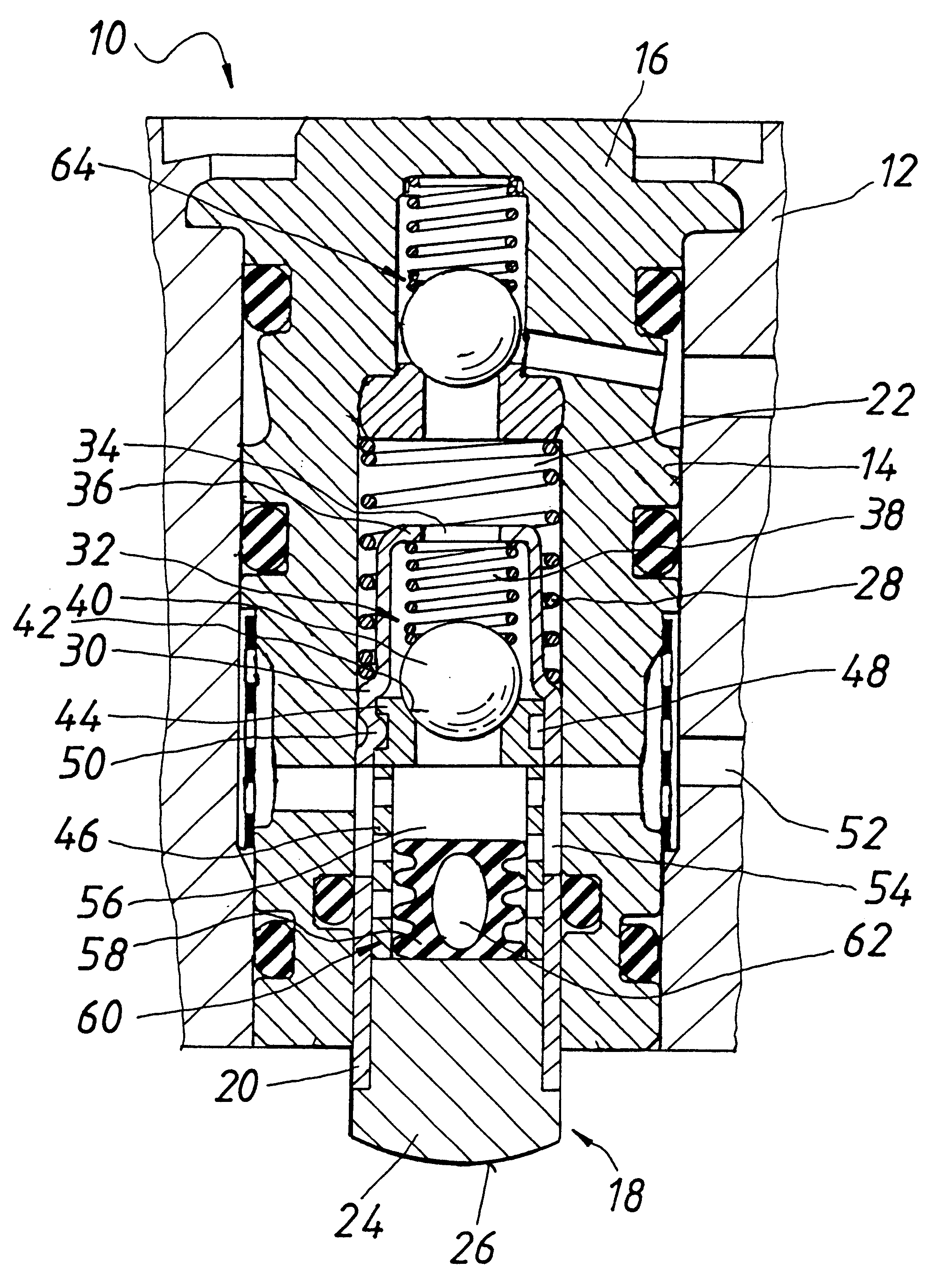
The piston pump of the invention, shown in FIG. 1 and identified overall by reference numeral 10, is intended in particular as a pump in a vehicle brake system and is used to control the pressure in wheel brake cylinders. Depending on the type of brake system, the abbreviations ABS, ASR, FDR and EHB are used for such brake systems. In the brake system, the pump serves for instance to return brake fluid from a wheel brake cylinder or a plurality of wheel brake cylinders to a master cylinder (ABS) and / or to pump brake fluid out of a supply container into a wheel brake cylinder or a plurality of wheel brake cylinders (ASR or FDR or EHB). In a brake system with wheel slip control (ABS or ASR) and / or a brake system serving as a steering aid (FDR) and / or an electrohydraulic brake system (EHB), the pump is needed. With the wheel slip control (ABS or ASR), locking of the wheels of the vehicle during a braking event involving strong pressure on the brake pedal (ABS) and / or spinning of the dr...


PUM


Abstract

The invention relates to a piston pump, which is intended for use as a return pump for a slip-controlled hydraulic vehicle brake system. To simplify the manufacture of a piston of the piston pump, the piston includes a thin sleeve.

Description

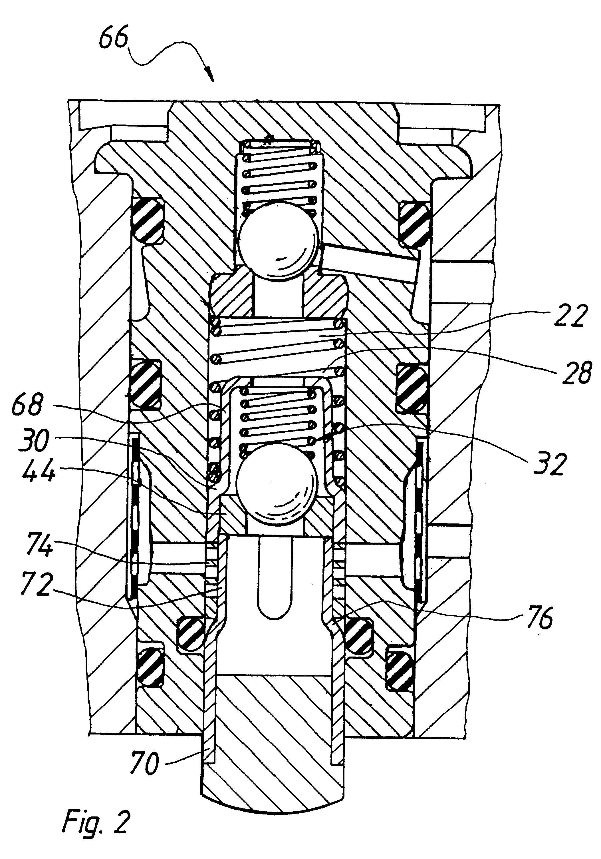
The invention relates to a piston pump which is intended for use as a return pump for a slip-controlled vehicle brake system.Many such piston pumps are known. As an example, German Patent Disclosure DE 40 27 794 A1 can be named. The known piston pump has a pump housing, into which a bush is inserted, in which bush a piston that can be driven to reciprocate is axially received. The piston is a part made by metal-cutting drilling and turning. The production of the piston is therefore complicated and expensive.OBJECT AND SUMMARY OF THE INVENTIONThe piston of the piston pump according to the invention has a sleeve or a plurality of sleeves that form a circumferential piston wall. This sleeve may be produced by reshaping a piece of pipe, for instance. The piston of the piston pump according to the invention can as a result be manufactured quickly and economically.Another advantage of the piston pump of the invention is the thin-walled embodiment of its piston because of the use of a slee...

Claims


Application Information

Patent Timeline
Patent Type & Authority Patents(United States)
IPC IPC(8): B60T8/40F04B53/10F04B9/02F04B53/14F04B9/04F04B53/00F04B53/12F04B1/04F04B1/00F04B11/00F04B39/00
CPCB60T8/4031F04B1/0421F04B53/14F04B11/0025F04B53/126F04B9/045F04B1/0408F04B1/0452F05B2210/11Y10S417/00
Inventor SCHULLER, WOLFGANGSINNL, ERWIN
Owner ROBERT BOSCH GMBH
Why Eureka
Try Eureka