Fluidtight zip fastener

Inactive Publication Date: 2002-02-05
YKK CORP
View PDF14 Cites 36 Cited by
  • Summary
  • Abstract
  • Description
  • Claims
  • Application Information

AI Technical Summary

Problems solved by technology

It has been found that not only the sealing, particularly when a pressure is applied to the sealing area, particularly if gastightness is desired, leaves much to be desired, but also the manufacture of such a zip fastener is complicated, time-consuming and therefore expensive due to the diff

Method used


Image

  • Fluidtight zip fastener
  • Fluidtight zip fastener
  • Fluidtight zip fastener

Examples


Embodiment Construction

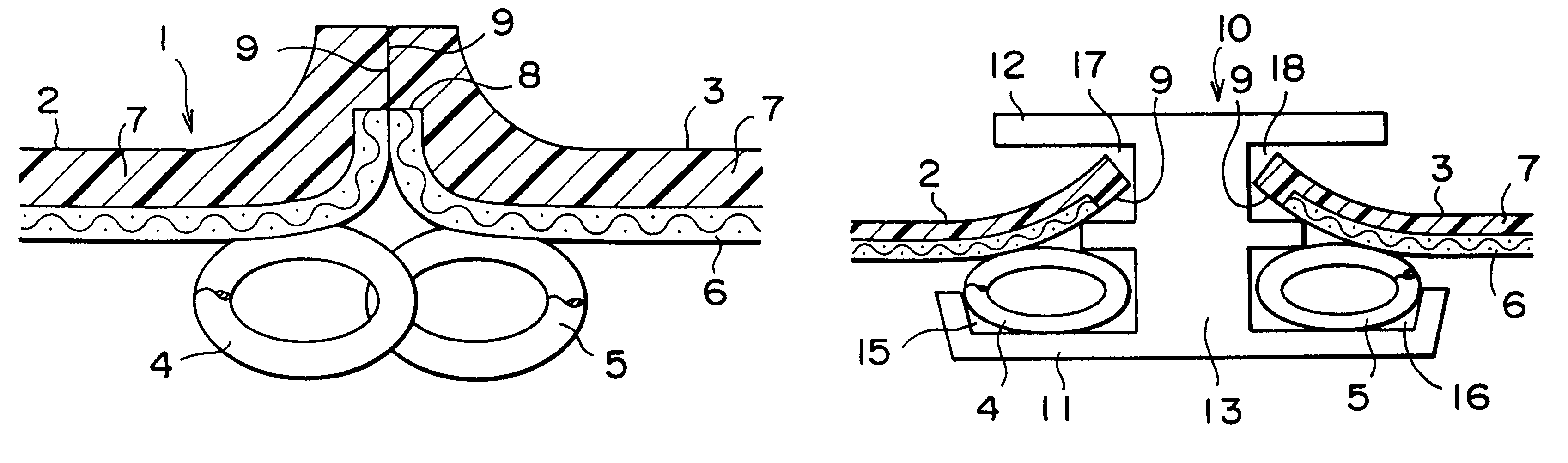
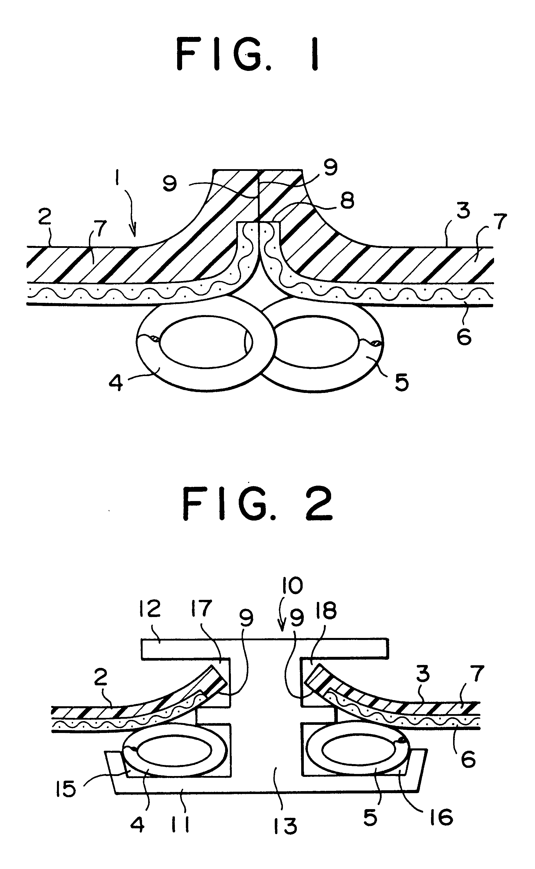
The zip fastener 1 illustrated in the drawings in conventional manner comprises two zip fastener carrying tapes 2, 3 with zip fastener member rows 4, 5 sewn thereto. Each of the carrying tapes 2, 3 comprises a base tape 6 made from a woven fabric, e.g. from polyester or some other synthetic material. However, it is also possible for the base tape 6 to be formed from cotton threads.

On its side remote from the coupling member rows 4,5, each base tape 6 is provided with a synthetic rubber, soft covering layer 7. This term in general manner covers elastomers, but thermoplastics can also be used for coating the base tape 6.

As is apparent from the drawings, the covering layer 7 projects over an end 8 of the base tape 6 and completely covers the same. Even in the case of prolonged use, this ensures that the base tape 6 cannot fray at this point.

It can also be seen that the continuous coupling member rows 4, 5 are sewn to the zip fastener carrying tapes 2, 3 in a spaced of offset position t...


PUM


Abstract

The fluidtight zip fastener comprises a pair of fluidtight zip fastener carrying tapes carrying the zip fastener coupling member rows and which are in each case formed by a base tape with a soft, synthetic rubber or similar covering layer. They engage on one another by their edge portions. The pair of continuous coupling member rows is sewn to the zip fastener carrying tapes in a spaced offset position transversely to the longitudinal edges of said carrying tapes in such a way that the press-contact edge portions of the soft covering layers are in contact with one another along a longitudinal plane, which intersects the zip fastener at a central axis thereof and runs at right angles to the zip fastener principal plane. The press-contact edge portions project over said longitudinal plane, when the coupling member rows are disengaged. The edge portions, when the coupling member rows are engaged, are bent away from the side carrying the coupling member rows so as to extend roughly at right angles to the zip fastener principal plane. The soft covering layers of the press-contact edge portions engage on one another under pressure action when the zip fastener is closed and thus ensure the fluidtightness condition.

Description

1. Field of the InventionThe invention relates to a fluidtight zip fastener, having a pair of fluidtight zip fastener carrying tapes carrying the zip fastener members and whose press-contact edge portions extending longitudinally engage on one another, each carrying tape comprising a base tape with a soft covering layer of synthetic rubber or the like, which covers at least one surface of the base tape in question, a pair of continuous coupling member rows being sewn to the zip fastener carrying tapes in a spatially offset position transversely to the longitudinal edges of the zip fastener carrying tapes in such a way that the press-contact edge portions of the soft covering layers are in contact with one another along a longitudinal plane which intersects the zip fastener at a central axis thereof and which is at right angles to the principal plane of the zip fastener, the press-contact edge portions of the zip fastener carrying tapes projecting over the longitudinal plane in quest...

Claims


Application Information

Patent Timeline
IPC IPC(8): A44B19/24A44B19/32A44B19/26
CPCA44B19/32Y10T24/2539Y10T24/2514Y10T24/252A44B19/26
Inventor NEUGEBAUER, HORST GOTTHARD
Owner YKK CORP
Why Eureka
Try Eureka