Method and apparatus for fitting a printing plate to a plate cylinder

a technology of printing plate and cylinder, which is applied in the field of printing machines, can solve the problems of damage to the printing surface, complicated apparatus, and high cost of plate sleeves of this typ

Inactive Publication Date: 2002-03-19
MANROLANAD AG
View PDF24 Cites 18 Cited by
  • Summary
  • Abstract
  • Description
  • Claims
  • Application Information

AI Technical Summary

Problems solved by technology

Such an apparatus is complicated and expensive, thus, production of plate sleeves of this type is correspondingly expensive.
The disadvantage in this case is that the tube rests on the pre-imaged surface of the printing plate and, as a result, can cause damage to the printing surface.

Method used


Image

  • Method and apparatus for fitting a printing plate to a plate cylinder
  • Method and apparatus for fitting a printing plate to a plate cylinder
  • Method and apparatus for fitting a printing plate to a plate cylinder

Examples


Embodiment Construction

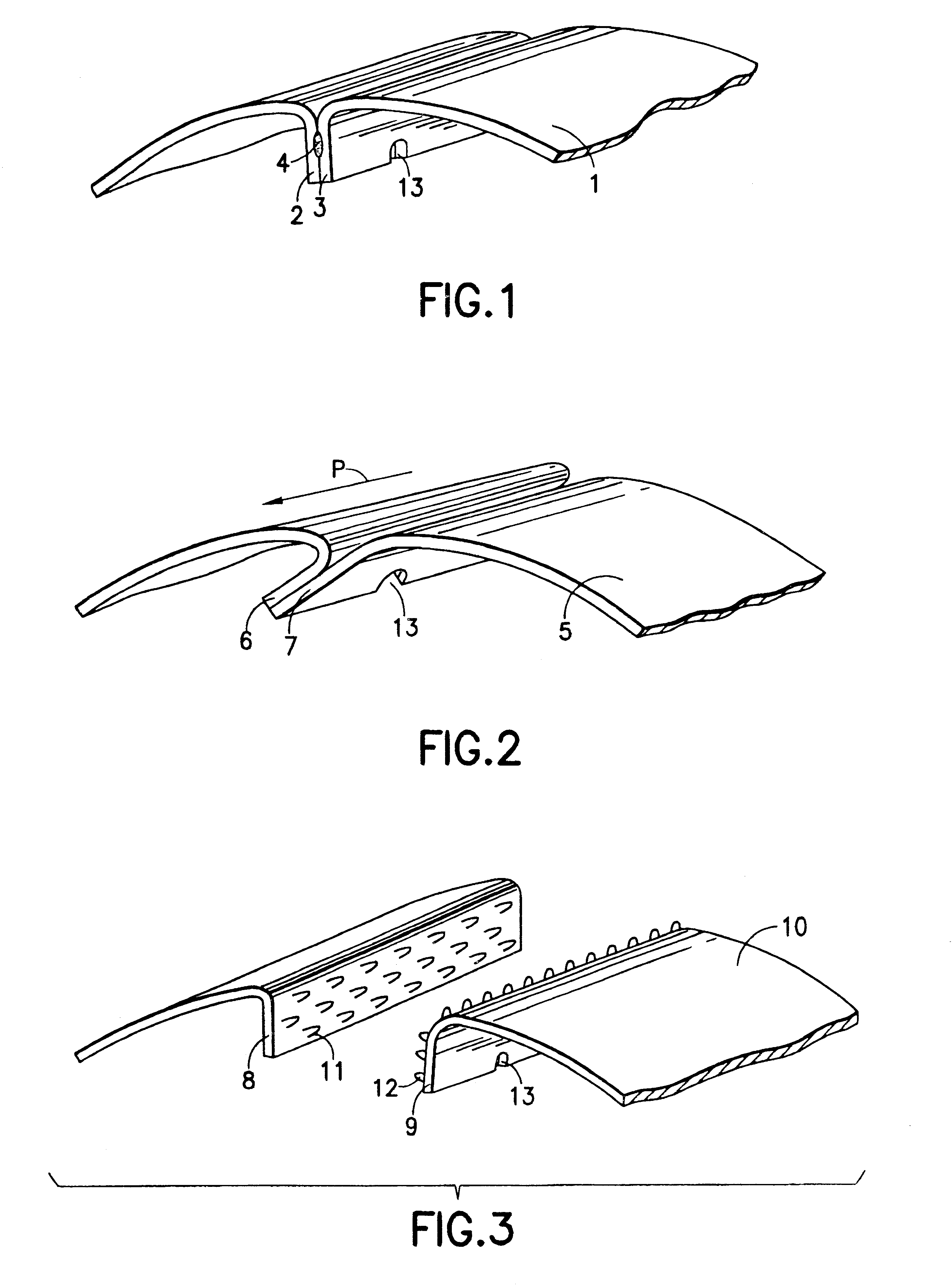
FIGS. 1 to 3 show, illustrated in part, printing plates which have been bent into a circular shape and whose plate legs, bent over at the edge, are firmly connected to each other. In detail, FIG. 1 shows a printing plate 1 whose leading and trailing plate legs 2 and 3, respectively, are bent over at right angles, rest on each other and, in this region, are connected to each other by electric resistance pressure welding. Electric seam welding is advantageously used to produce a continuous weld 4. However, spot welding is also possible.

FIG. 2 shows a printing plate 5 having leading and trailing plate legs 6 and 7, respectively, bent over obliquely at the edge. Here, the two legs 6, 7 of the plate are bonded over their length using their faces pointing towards each other, for which purpose the rough surface is extremely suitable. In an exemplary embodiment, a liquid adhesive is used, which is applied by means of gun or spray application. The use of double-sided adhesive tape is also po...


PUM


Abstract

A method and apparatus for fitting a printing plate to a plate cylinder where the printing plate is bent into a circular shape and fixed in this form by leading and trailing legs of the plate being firmly connected to each other. The printing plate shaped in this way is subsequently axially pushed onto the plate cylinder from the free side of the plate cylinder.

Description

1. Field of the InventionThe invention relates to printing machines, and more particularly to a method and an apparatus for fitting a printing plate, especially an offset printing plate, to an overhung plate cylinder of a rotary printing machine.2. Description of the Related ArtDE 43 15 909 A1 shows a printing unit in which the plate cylinders are fitted with printing-plate sleeves. During printing operation, the plate cylinders are mounted on both sides in side walls. In order to change the printing-plate, supporting elements are removed from one side wall, after which the plate cylinders are overhung in the other side wall. The plate sleeves can than be drawn off the plate cylinders at the exposed sides of the latter and changed.Plate sleeves advantageously consist of stainless steel, nickel or a nickel alloy, for example Hastelloy, and are well suited for erasable image-setting. In addition, these materials have good strength values. Plate sleeves of this type are clamped onto th...

Claims


Application Information

Patent Timeline
Patent Type & Authority Patents(United States)
IPC IPC(8): B41F27/12B41F27/10
CPCB41F27/12B41P2227/21
Inventor DAUER, HORSTDILLING, PEERPETERSEN, GODBERSCHNEIDER, JOSEF
Owner MANROLANAD AG
Why Eureka
Try Eureka