Support for heat exchanger tubes

a technology for heat exchangers and tubes, applied in the field of support for tubes and fins, can solve the problems of reducing the surface area of fins, increasing costs and reducing the cost of fins, and causing serious damag

Inactive Publication Date: 2002-03-19
L & M RADIATOR
View PDF30 Cites 29 Cited by
  • Summary
  • Abstract
  • Description
  • Claims
  • Application Information

AI Technical Summary

Problems solved by technology

Utilization of a central header does, however, substantially increase cost and reduce fin surface area, thereby requiring a larger heat exchanger to achieve a given heat transfer capacity.
Movement and vibration of the tube-and-fin assemblies, as a result of operation or impact, can produce serious damage due to (i) excessive movement or deflection of individual assemblies, or (ii) contact between adjacent assemblies.
In addition, loss of fin surface area such as by removal of fins from the flow tube, renders the heat exchanger less effective for a particular application.
The use of continuous strip supports, unfortunately, sub

Method used


Image

  • Support for heat exchanger tubes
  • Support for heat exchanger tubes
  • Support for heat exchanger tubes

Examples


Embodiment Construction

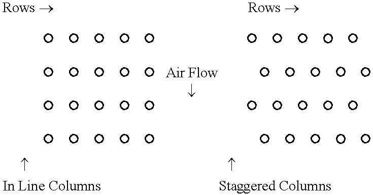
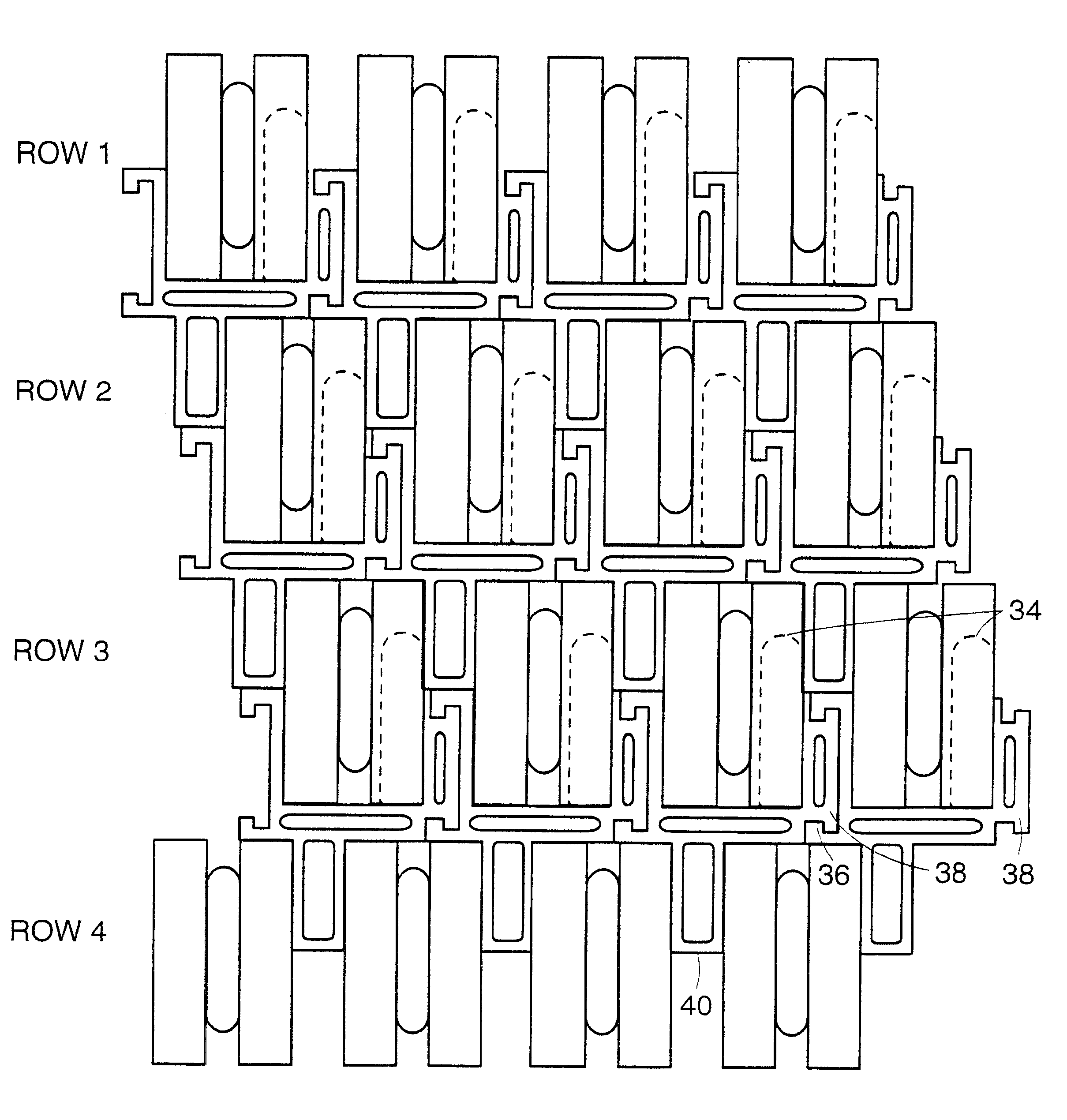
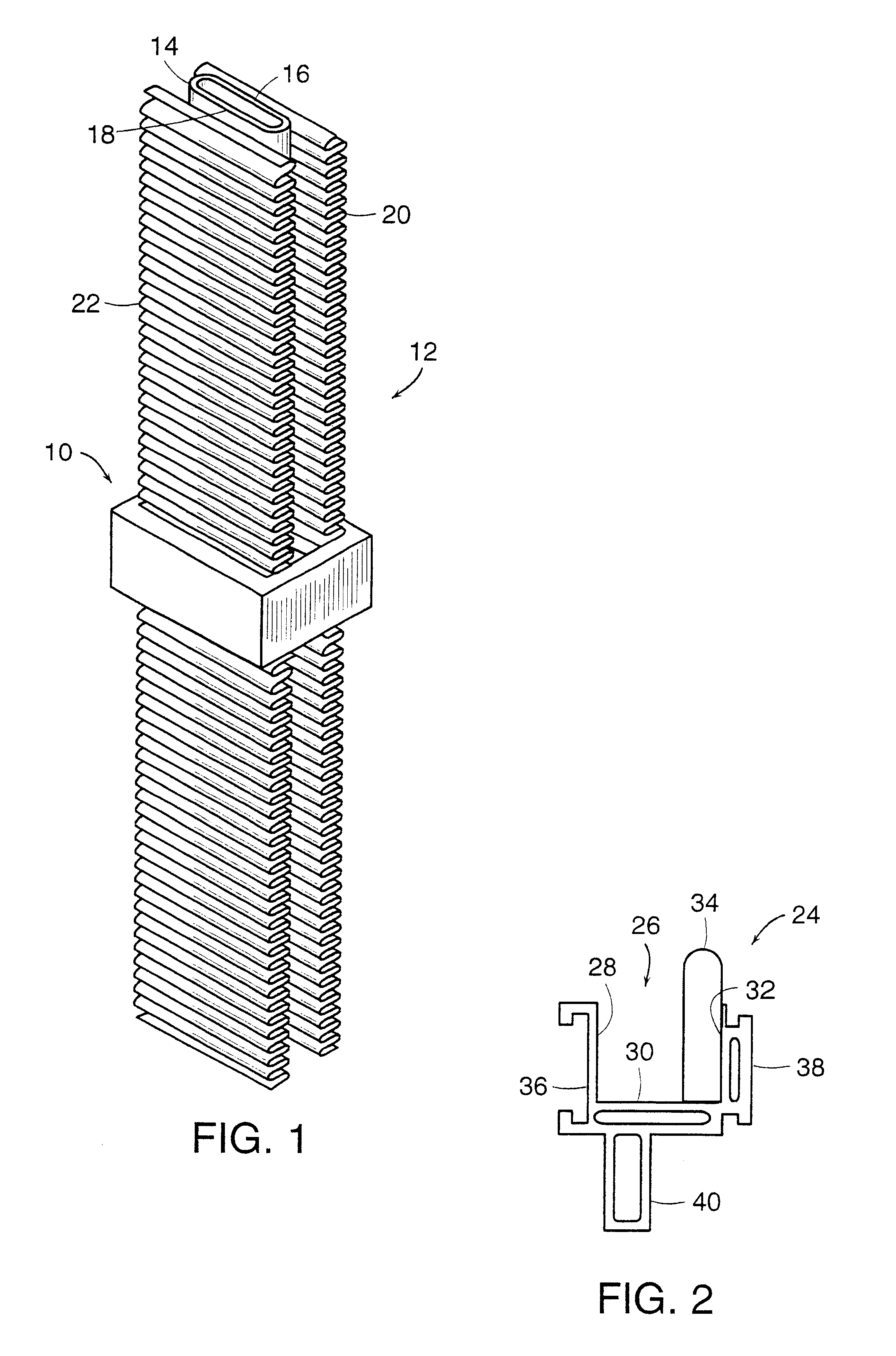
The principles of the present invention may be applied with particular advantage to provide an improved support for use with tube-and-fin assemblies as commonly found as part of a heat exchanger. More particularly, the heat exchanger includes a multiplicity of tube-and-fin assemblies 12, an example of which is depicted in FIG. 1, which are arranged in rows and columns and interconnected between upper and lower headers (not shown). The rows extend longitudinally across the heat exchanger, substantially perpendicular to the direction of air flow, and the columns are substantially perpendicular to the rows. The columns, for example, may be "in-line" or "staggered" (also referred to herein as "off set") as shown below (top view of tube-and-fin assemblies): ##STR1##

It is to be understood that alternate staggered designs are within the scope of the present invention such as a staggered design where tube-and-fin assemblies of every fourth row are aligned.

FIG. 1 depicts a prior art tube-and...


PUM


Abstract

A novel individual support for a heat exchanger is disclosed which frictionally engages the outer surface of a tube-and-fin assembly and provides for interlocking of the supports. The novel support includes an alignment probe to facilitate installation and to prevent axial movement of the support.

Description

1. Field of the InventionEmbodiments of the present invention relate generally to a heat exchanger having tube-and-fin assemblies, such as found in a diesel engine cooling system, and more particularly to a support for the tube-and-fin assemblies such that alignment of the tubes and the overall strength and rigidity of the heat exchanger is enhanced.2. Description of Related ArtA heat exchanger includes a multiplicity of tube-and-fin assemblies. The tube-and-fin assemblies are mounted in headers, arranged in columns and rows, and interconnected to receive and pass a heating / cooling fluid (dependent upon application). These tube-and-fin assemblies may be of the removable type or soldered in place. In certain environments, the tube-and-fin assemblies must have considerable length in order to provide sufficient heat transfer. The rigidity of the assembly decreases with increased length, and thus it is often necessary in such applications to include a central header, in essence splittin...

Claims


Application Information

Patent Timeline
IPC IPC(8): F28F9/013F28F9/007
CPCF28F1/02F28F9/0138F28F1/126F28F2275/14
Inventor JANEZICH, ROBERTDOSEN, TODD G.
Owner L & M RADIATOR
Why Eureka
Try Eureka