Weed stick spray

Inactive Publication Date: 2002-04-09
PANINT ELECTRONICS
View PDF9 Cites 23 Cited by
  • Summary
  • Abstract
  • Description
  • Claims
  • Application Information

AI Technical Summary

Problems solved by technology

That is, an operator using these related art devices could inadvertently not apply the correct amount herbicide in any situation by either not forcing a displacement handle down with enough force or the proper distance.

Method used


Image

  • Weed stick spray
  • Weed stick spray

Examples


Embodiment Construction

)

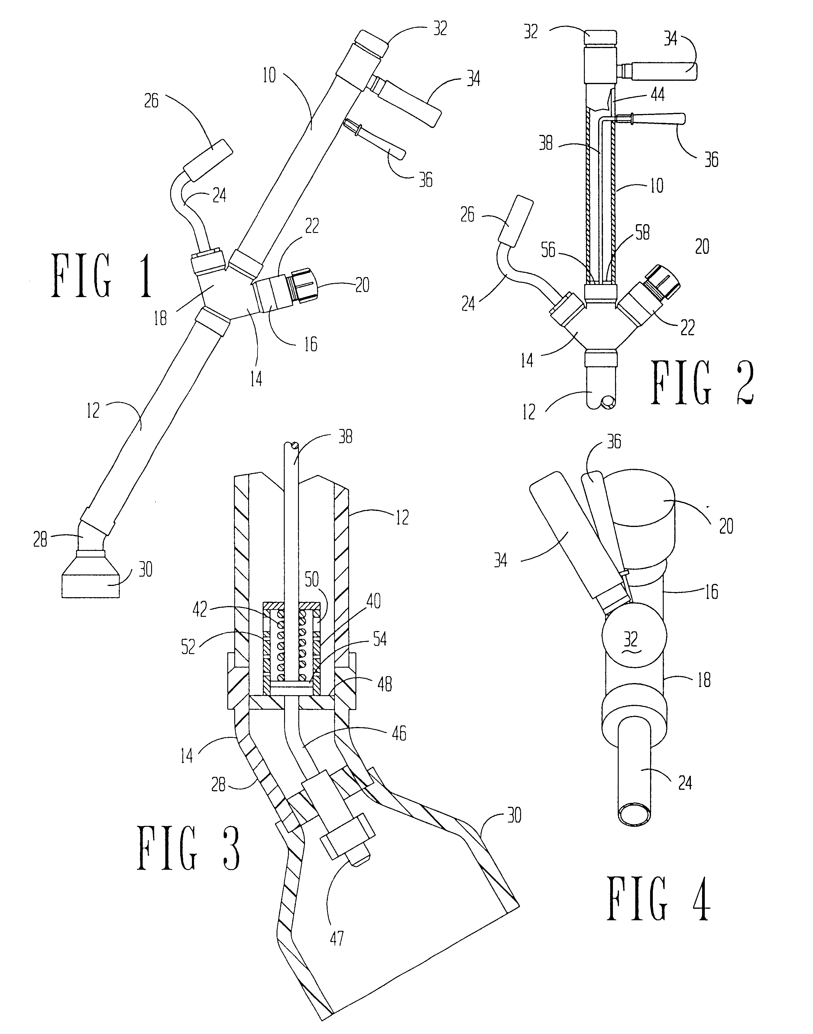
Referring to the drawings, particularly FIG. 1, it may be seen that one embodiment of this invention uses standard plastic pipe or tubing with different fittings as the applicator.

As may be seen, top tube 10 is connected to chemical tube 12. These tubes are connected together with a special branch fitting 14. The branch fitting 14 has cap branch 16 and handle hand hold branch 18. The cap branch has screw cap 20 which mates with threads on cuff 22 so that the cap may be removed and herbicide poured therein to fill the chemical tube 12.

The hand hold branch 18 has a hand extension 24 securely fixed thereto. Rubber hand grip 26 telescopes over the end of extension 24. Upper tube is fitted to branch fitting 14 coaxial with the chemical tube 12.

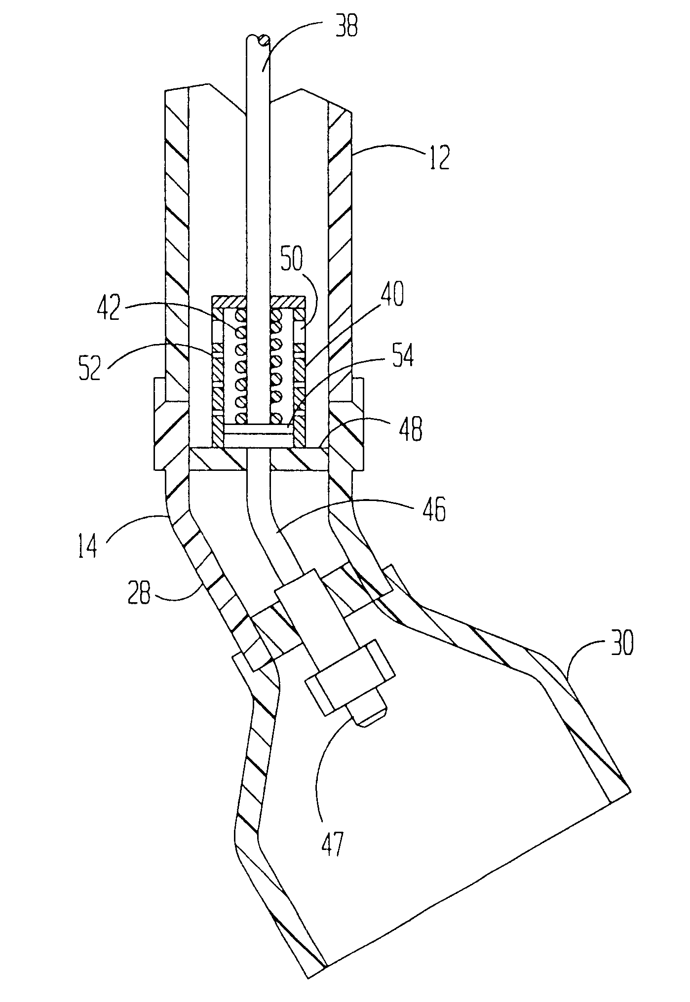
At the bottom of the chemical tube 12, bend 28 is attached. Bell 30 is attached to the end of the bend 28. The axis of the bell 30 is about a 30o angle to the axis of tubes 10 and 12.

The top of the tube is closed with permanent cap as top cap 32. ...


PUM


Abstract

A herbicide applicator is in the form of an extended tube with a bell on the bottom to restrict the spray of herbicides. The tube includes a pump at the bottom which is connected to a nozzle within the bell. The pump is operated by a rod extending to the top of the tube. The rod is spring biased in a down position. The pump is operated by lifting the rod at the top and releasing the rod. The spring in the pump forces a measured amount of herbicide upon the release.

Description

(1) Field of the InventionThis invention relates to the selective application of herbicides. People who apply herbicides have ordinary skill in this art.(2) Description of the Related ArtAs public awareness of the dangers and risks associated with broadcast application of herbicides increases, the public has become increasingly interested in herbicide application methods that reduce the overall amount of chemical released into the environment.Most of the related art patents in this field were issued in the late 1950's. Eg. DICKSON 2,841,923. While many of these inventions may have been conceptually viable before they were marketable, most also have the inherent characteristic that the amount or volume of herbicide applied to the particular plant within the spray shield was dependent upon a uniform application of force and duration by the operator of the device. That is, an operator using these related art devices could inadvertently not apply the correct amount herbicide in any situ...

Claims


Application Information

Patent Timeline
IPC IPC(8): A01M21/04A01M21/00
CPCA01M21/043
Inventor SMOOT, JERRY
Owner PANINT ELECTRONICS
Why Eureka
Try Eureka