
Tape printer

a tape printer and tape cartridge technology, applied in the direction of typewriters, printing, inking apparatus, etc., can solve the problems of inability to disassemble the lid of the apparatus, unstable tape cartridges, and troublesome operation

Inactive Publication Date: 2002-04-09
SEIKO EPSON CORP
View PDF8 Cites 39 Cited by
  • Summary
  • Abstract
  • Description
  • Claims
  • Application Information

AI Technical Summary

Benefits of technology

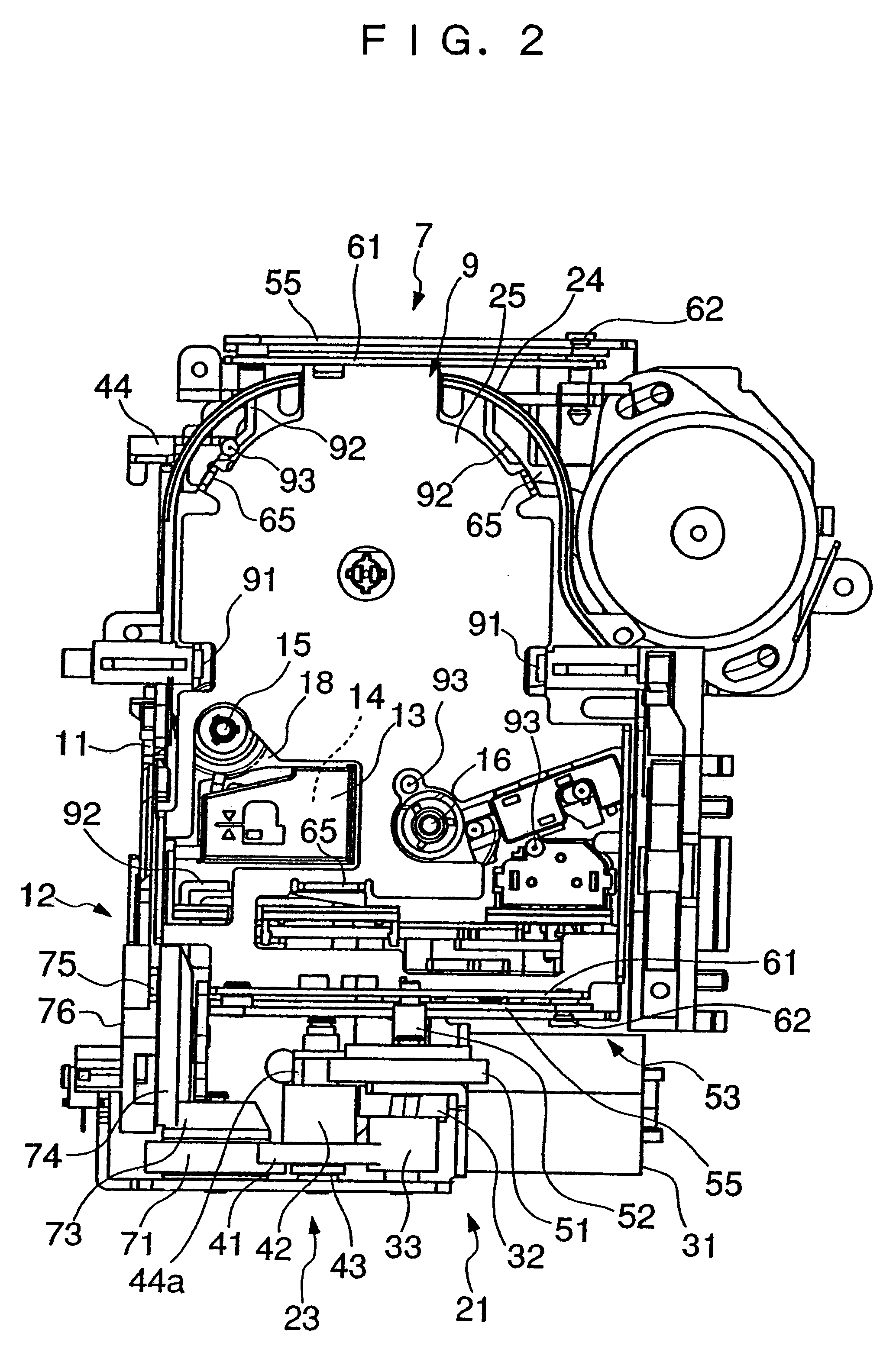
According to this construction, the lift plate of the ejection mechanism is positioned away from a tape cartridge seated on the seat portion when it is in a standby state. Therefore, the tape cartridge is used for printing in a state seated on the seat portion, and the lift plate receives the tape cartridge from the seat portion as it moves upward, to lift the same from the cartridge compartment. The seat portion is fixedly arranged, so that the tape cartridge seated on the seat portion is stably and accurately positioned for printing.
According to this construction, it is possible to use the holding nail serving as a support member, not only to immovably hold a tape cartridge on the seat portion, but also to hold a lifted tape cartridge in the lifted state. Further, since the holding nail also serves as a support member, an increase in number of component parts is prevented.
According to this construction, the three-point support by the three seat members makes it possible to hold a tape cartridge on the seat portion in a stable state without making the same shaky.
According to this construction, the ejection mechanism can be operated automatically. Therefore, the ejection mechanism is not required to be interlocked with the lid of the cartridge compartment, or the like, which makes it possible to drive the ejection mechanism only when required.

Problems solved by technology

In the conventional tape printing apparatus, the ejection plate is at its uppermost position when a tape cartridge has been removed, so that when a tape cartridge is mounted, it is required to push the tape cartridge deep into the cartridge compartment together with the ejection plate, which makes the operation troublesome.
Further, if the lid is closed erroneously when the ejection plate is at its uppermost position, an inconvenience can occur that the lid is disassembled from the apparatus.
This tends to make the supported tape cartridge unstable as to a level state (levelness) and shaky due to the structure of the ejection mechanism, which makes it difficult to print accurately on a printing tape.

Method used


Image

  • Tape printer
  • Tape printer
  • Tape printer

Examples


Embodiment Construction

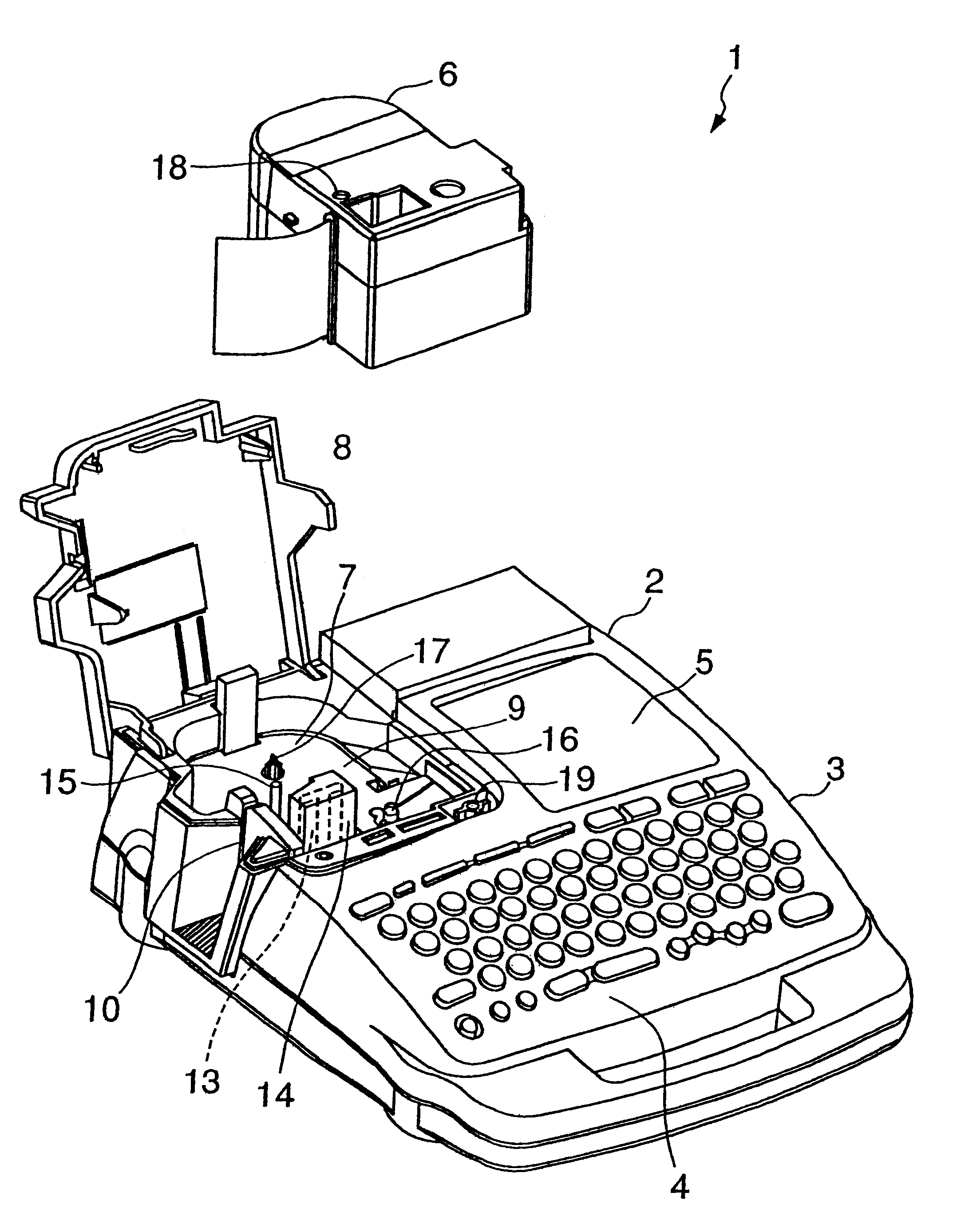
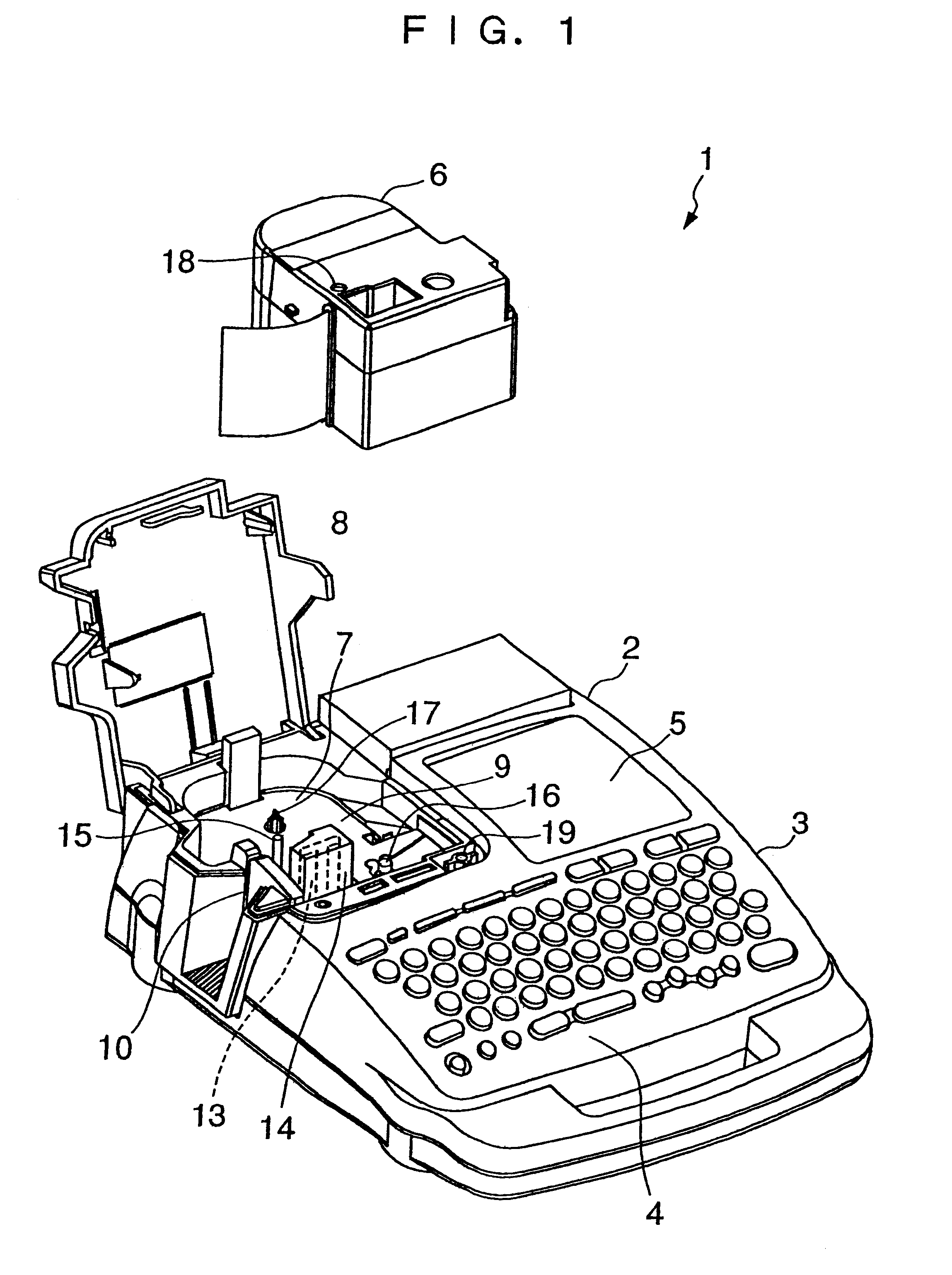
The invention will now be described in detail with reference to the drawings showing a tape printing apparatus according to an embodiment thereof. The tape printing apparatus is capable of printing desired characters and figures on a strip of printing tape and cutting off a printed portion of the printing tape. The cut-off piece of the printing tape is used as a label to be affixed to a document file or the like. That is, the tape printing apparatus makes a label printed with characters and figures from a strip of plain printing tape. In this case, the plain printing tape and an ink ribbon as consumable articles are contained in a tape cartridge, and supplied to the apparatus via the tape cartridge.

Referring first to FIG. 1, the tape printing apparatus 1 has a body 2 having an apparatus casing 3 comprised of upper and lower divisional portions. The apparatus casing 3 has a key entry block 4 arranged in the front portion thereof, a liquid crystal display 5 arranged in the rear right-...


PUM


Abstract

There is provided a tape printing apparatus in which a cartridge-ejecting function by an ejection mechanism and a cartridge-holding function by a cartridge compartment are separated from each other based on a simple construction. In the tape printing apparatus including a cartridge compartment for removably mounting a tape cartridge therein, and an ejection mechanism for lifting the tape cartridge mounted, from the cartridge compartment, the cartridge compartment has a bottom thereof formed with a seat portion for seating thereon the tape cartridge in a mounted state, and a lift plate of the ejection mechanism for lifting a tape cartridge is positioned away from the tape cartridge seated on the seat portion when the lift plate is in a standby state. This construction makes it possible to separate the cartridge-ejecting function implemented by the ejection mechanism and the cartridge-holding function by the cartridge compartment from each other, thereby preventing the ejection mechanism from adversely affecting printing operation.

Description

This invention relates to a tape printing apparatus including an ejection mechanism for lifting a mounted tape cartridge from a cartridge compartment.A tape printing apparatus including a conventional ejection mechanism has been proposed e.g. in Japanese Laid-Open Patent Publication (Kokai) No. 9-277678. The ejection mechanism is comprised of an ejection plate (lift plate) for supporting a tape cartridge in a cartridge compartment, an X-shaped link for lifting and lowering the ejection plate, and a spring for causing the X-shaped link to operate.In the apparatus, when a lid-opening button is depressed, a lid of the cartridge compartment is caused to pop up to be half opened. Then, when the lid is manually fully opened from this state by the user, the ejection mechanism is unlocked, and the urging force of the spring causes the X-shaped link to operate to lift the ejection plate, whereby the tape cartridge is lifted from the cartridge compartment.Reversely, when a tape cartridge is p...

Claims


Application Information

Patent Timeline
IPC IPC(8): B41J15/04B41J3/407
CPCB41J15/044B41J3/4075
Inventor HASHIMOTO, AKIRAFURUYA, YOSHIKIYO
Owner SEIKO EPSON CORP
Learn More