PES linearization scheme for disk drive servo using small excitation bode measurements

a linearization scheme and disk drive technology, applied in the field of small excitation bode measurement, can solve the problems of increased likelihood of errors in write and read operations, fewer no longer vary linearly in typical servo burst amplitudes, etc., to achieve more accurate read and write operations.

a linearization scheme and disk drive technology, applied in the field of small excitation bode measurement, can solve the problems of increased likelihood of errors in write and read operations, fewer no longer vary linearly in typical servo burst amplitudes, etc., to achieve more accurate read and write operations.

US6369971B1Inactive Publication Date: 2002-04-09SEAGATE TECH LLC

Image

  • PES linearization scheme for disk drive servo using small excitation bode measurements
  • PES linearization scheme for disk drive servo using small excitation bode measurements
  • PES linearization scheme for disk drive servo using small excitation bode measurements

Examples


Embodiment Construction

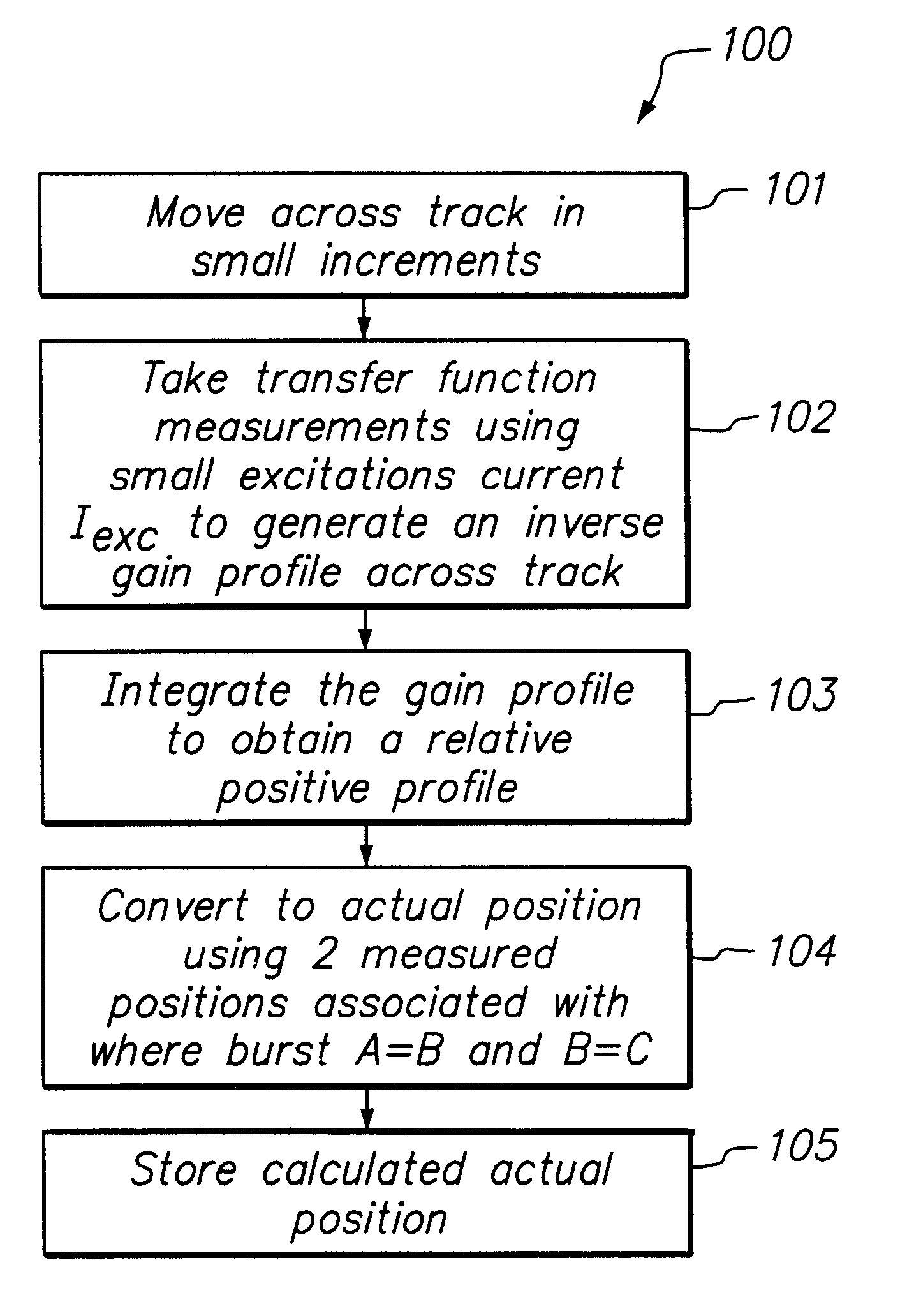
FIG. 3 illustrates a PES linearization system provided in accordance with the principles of this invention. FIG. 4. illustrates a flow diagram of a PES linearization method 100 for operating PES linarization system 10 of FIG. 3 in accordance with the principles of this invention. In step 101, a sinusoidal electrical current I.sub.exc is injected into a rotator coil 11 of head element 12 at a frequency .function. and at a sufficient amplitude to cause a corresponding small movement x of head element 12 at preferably about 2-3% of track distance. Head element 12 is thus moved across a track of a storage device (not shown), such as a disk drive, in small increments while measuring the transfer function from excitation current to measured burst amplitude difference at frequency f using a Discrete Fourier Transform (DFT), wherein ##EQU1##

where

f=frequency of excitation current

N=number of sample points

T=sample time

If ##EQU2##

from Eqn 1 is described as the gain, then the inverse gain is: ##...


PUM

PropertyMeasurementUnit
currentaaaaaaaaaa
poweraaaaaaaaaa
excitation currentaaaaaaaaaa

Abstract

A PES linearization scheme using small excitation bode measurements is provided to account for non-linearity characteristics during measurements of head element positions so to generate a more accurate read and write operation by a head element of a disk drive assembly. The PES linearization scheme of this invention provides making gain measurements as the head element moves across the track, and then integrating the result to get a relative PES profile. By then finding two points on the profile a known distance apart, we can multiply the profile by the appropriate gain factor to get an absolute PES profile. This profile can be then be used as a look up table to convert raw PES numbers into actual position.

Description

This invention generally relates to methods of determining positions of the head element in a storage medium assembly to maximize the accuracy of a read or write operation of that head element, more particularly the invention relates to methods of measuring the non-linear relationship between measured servo burst amplitudes and head position to improve the accuracy of the servo positioning system.BACKGROUND OF INVENTIONIn a typical disk drive assembly, methods of determining head element positions to enable accurate read and write operations include having a servo writer write track and burst data information into each of various spoke regions distributed at radial intervals across each track of a disk medium. The track and burst information at each spoke region is then used to identify a corresponding radial position on that track. As illustrated in FIG. 1, a prior technique to determine a radial position of the head element on a particular track is to measure the read-back amplitu...

Claims


Application Information

Patent Timeline
09 Apr 2002
Publication
US6369971B1
IPC
G11B5/55
CPC
G11B5/5526
Inventors
EVERETT, TIMOTHY J.