Downcomer to a plate column

a technology of downcomer and plate column, which is applied in the direction of combustion air/fuel air treatment, separation process, carburettant air, etc., can solve the problems of only slowly renewing liquid and impaired plate effectivity

Inactive Publication Date: 2002-04-16
SULZER CHEMTECH AG
View PDF19 Cites 24 Cited by
  • Summary
  • Abstract
  • Description
  • Claims
  • Application Information

AI Technical Summary

Problems solved by technology

As a result of this onward conduction of the liquid, an unfavorable "shadow region" results beneath the cup: Liquid is moved away out of this region through the momentum of the onwardly conducted liquid so that, on the one hand, the liquid level is lowered t

Method used


Image

  • Downcomer to a plate column
  • Downcomer to a plate column
  • Downcomer to a plate column

Examples


Embodiment Construction

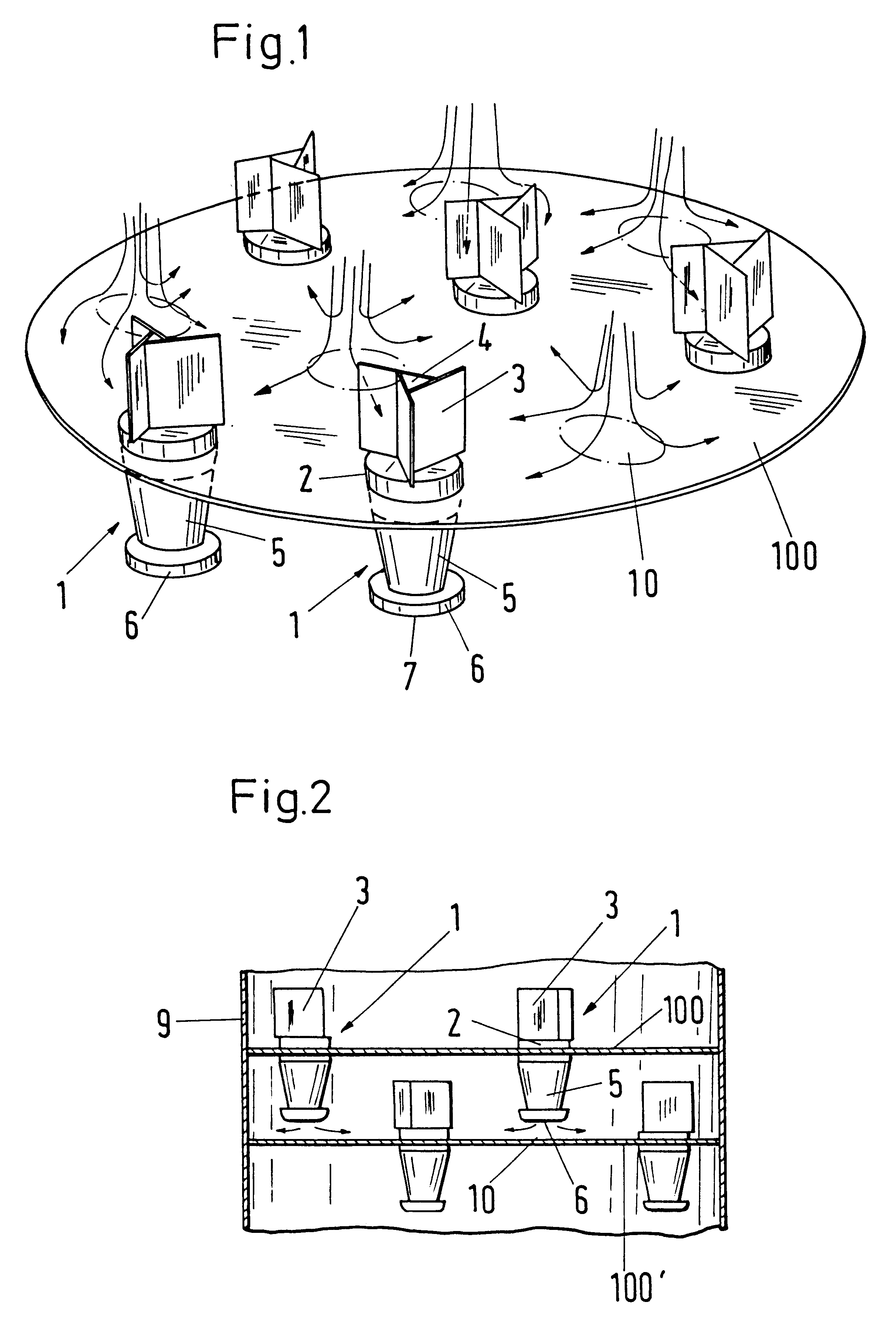
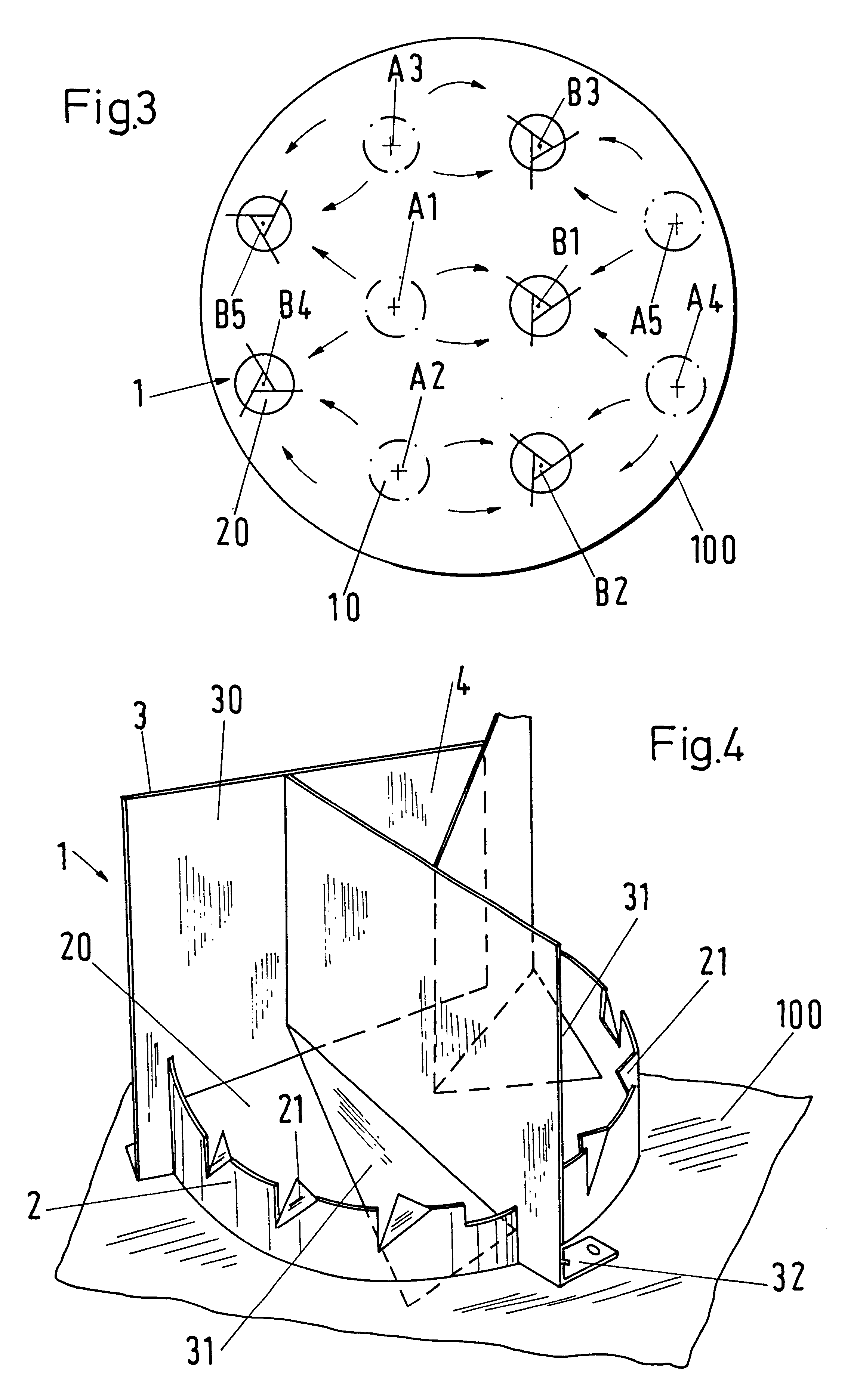
The plate 100 shown in FIG. 1 has five downcomers 1. The areas 10 illustrated in chain-dotted lines are the approach points, at which the runback of the adjacent plate is incident on the plate 100. The arrows indicate the flow direction of the onward flowing liquid. A gas or vapor enters into the liquid from below through non-illustrated gas passage apertures (perforations, valves, bells) so that an exchange of material and heat can take place. The gas temporarily contained in the liquid forms a liquid / gas mixture with it.

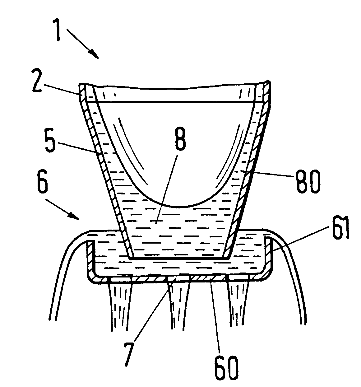
The downcomer 1 is designed to be largely centrally symmetric with respect to an axis which points in the direction of the column. Each downcomer comprises an overflow weir 2, a run-out opening 20 and a deflection element 3 for the inflowing liquid / gas mixture. A chimney 4 is located between the deflection elements 3 through which the gas separated out of the mixture can flow off upwardly. The separation of the gas and the liquid takes place in a passage part 5 of ...


PUM


Abstract

A downcomer for a plate column, which is largely centrally symmetrically formed with respect to an axis pointing in the column direction, having: a) a run-out aperture which is located within an overflow weir and which contains at least one of: deflection elements, and elements on the overflow weir, for an inflowing liquid/gas mixture for the development of a circular flow; b) a passage part which leads downward; and (c) a cup which is provided at the lower end of the passage part for accumulating the liquid flowing away. The cup contains a plurality of apertures which are designed and arranged in such a manner that a largely uniform distribution of the liquid flowing away results.

Description

1. Field of the InventionThe invention relates to a downcomer for a plate column and to a plate column with downcomers of this kind.2. Description of the Prior ArtA downcomer of this kind, a so-called "rotary liquid run-out apparatus", is disclosed in DE-A 2 140 899; in this downcomer the liquid running back is set into a rotary movement. In a downcomer the runback flows from one plate ("vapor / liquid contact plate") to the next lower one. Gas (or vapor) which is carried along must be separated from the runback in the downcomer. In the named apparatus the liquid / gas mixture flowing into the downcomer is guided by guide blades in such a manner that the separation process is accelerated thanks to the resulting rotary motion and as a result of the centrifugal force. A cup, which forms the lower closure of the downcomer and which is arranged at a distance above the next lower plate, allows the liquid flowing out of the downcomer to accumulate so that a short-circuit flow of the gas throu...

Claims


Application Information

Patent Timeline
IPC IPC(8): B01D3/14B01D3/20B01D3/00
CPCB01D3/20
Inventor GERLA, JOHANNESVAN WESTENDORP, HENK BERT
Owner SULZER CHEMTECH AG
Why Eureka
Try Eureka