Cap frame drive assembly and method

a technology of drive assembly and frame, which is applied in the direction of automatic machines, embroideries, textiles and paper, etc., can solve the problems of several hours of downtime for attachment and changeover, waste of machine downtime and labor, etc., and achieves the effect of simple machine screws or bolts, little time, and quick learning

Inactive Publication Date: 2002-04-23
EFP INC
View PDF9 Cites 14 Cited by
  • Summary
  • Abstract
  • Description
  • Claims
  • Application Information

AI Technical Summary

Benefits of technology

It is a further objective of the present invention to provide a drive base which can be permanently attached for long runs to a pantograph with simple machine screws or bolts in little time.

Problems solved by technology

As it is rare to embroider or sew on only curved articles, most machine operators are required to change from flat goods to caps often, even though such changes require wasted machine downtime and labor.
While drive frame assem

Method used


Image

  • Cap frame drive assembly and method
  • Cap frame drive assembly and method
  • Cap frame drive assembly and method

Examples


Embodiment Construction

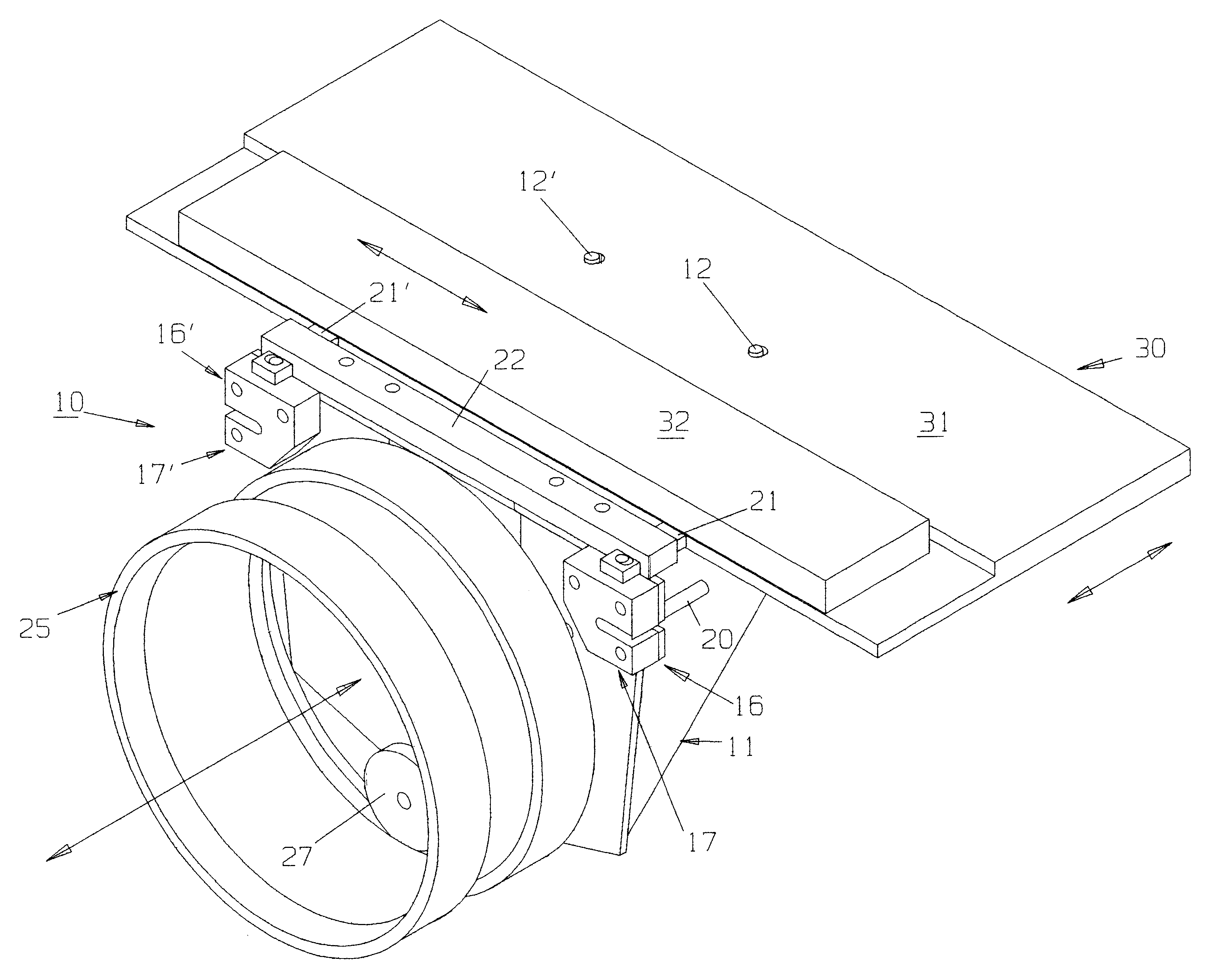
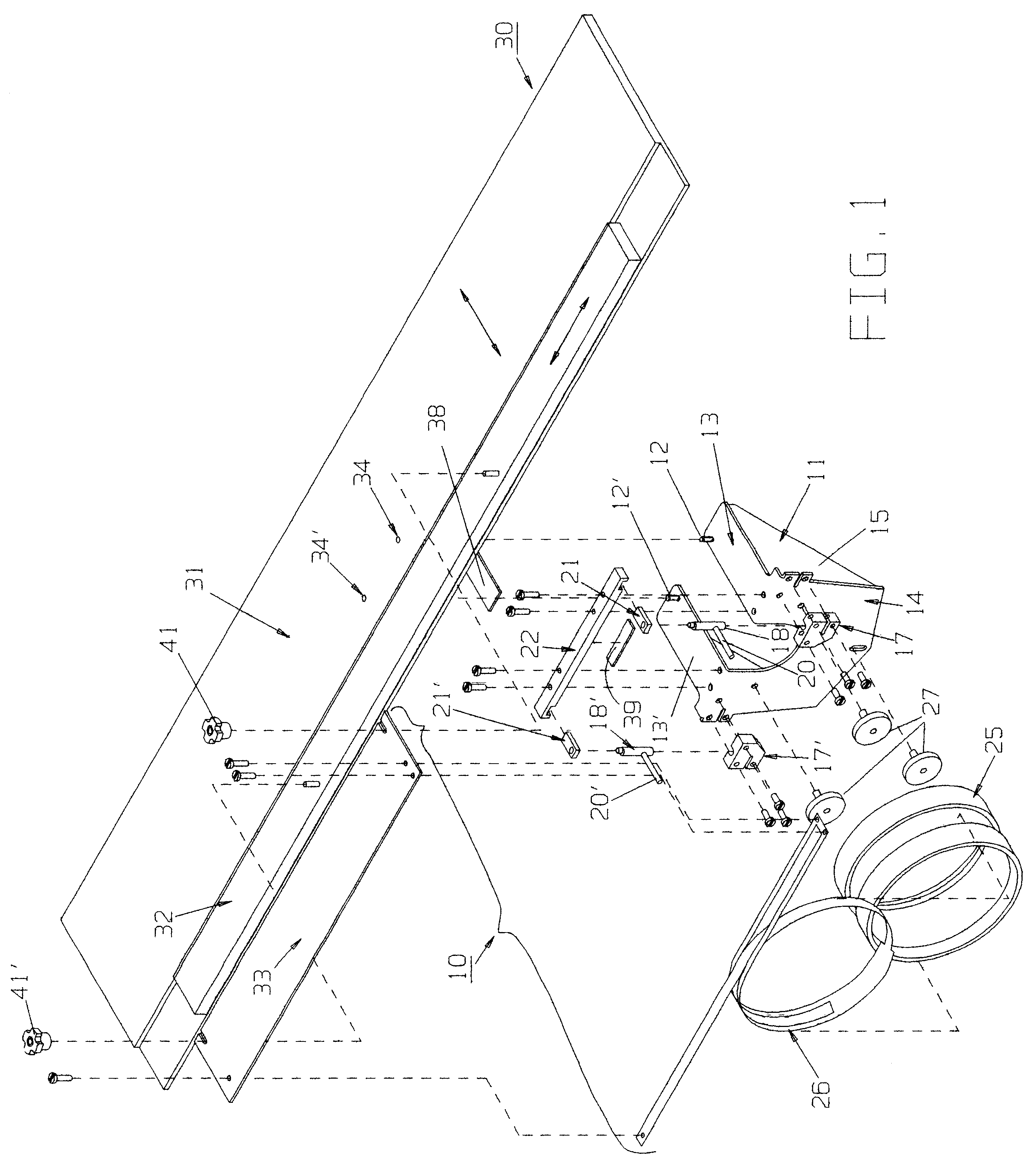
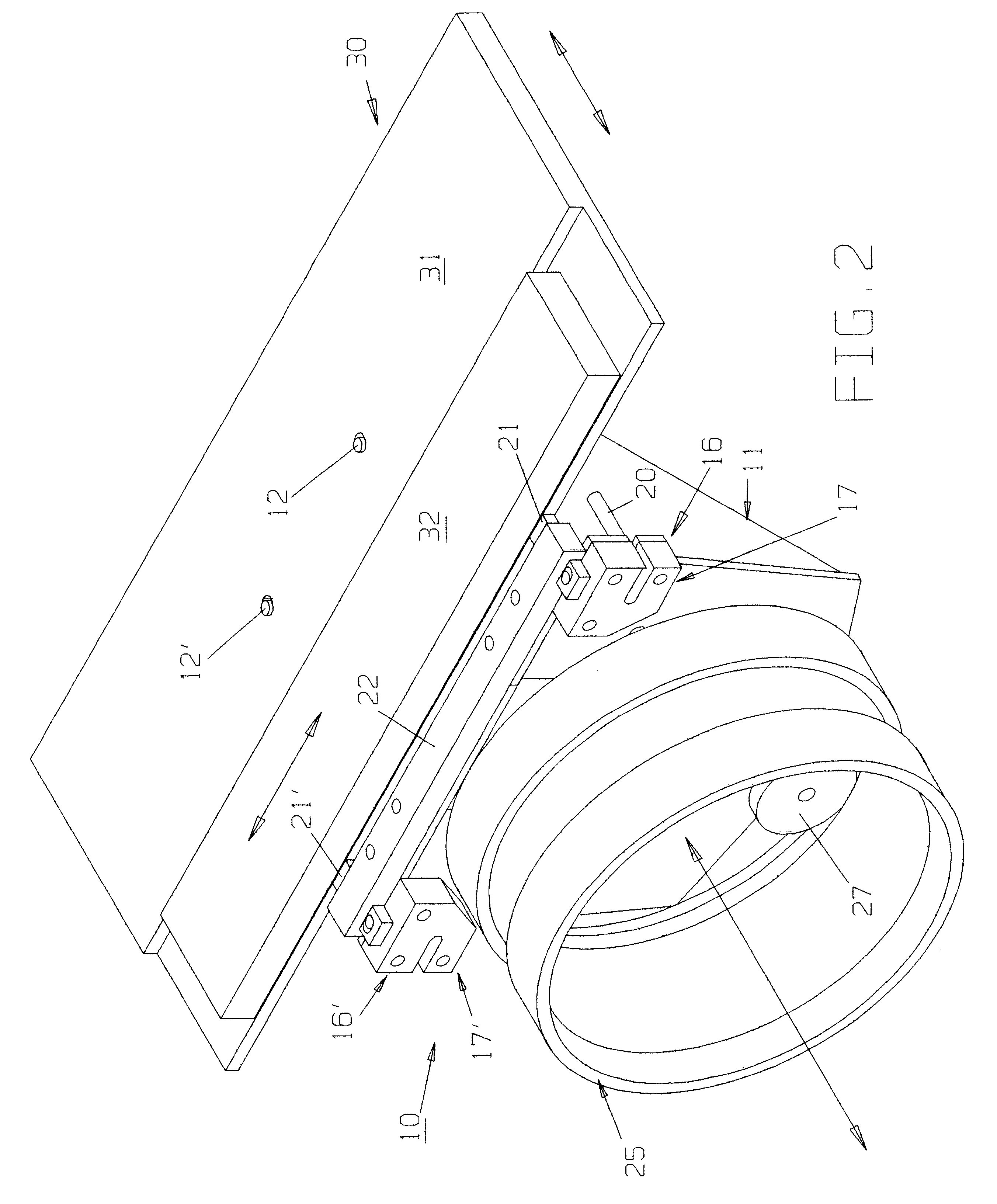
For a better understanding of the invention and its method of operation, turning now to the drawings, FIG. 1 demonstrates preferred cap frame drive assembly 10 in exploded fashion, apart from pantograph 30 which, as would be understood would be connected to a commercial multi-head sewing machine as used for embroidering, sewing and the like. Cap frame drive assembly 10 is shown for one sewing station, though a plurality would generally be used, includes drive cylinder 25 for holding curved articles such as baseball caps or the like thereon for stitching, sewing and embroidering purposes. Also included are belt 26, wheels 27, drive base 11, cam mechanism 16, 16' (within mounting blocks 17, 17' respectively) with cams 18, 18' with levers 20, 20', cam followers 21, 21', cam follower guide 22, leveling pad 39, rotational drive platform 33, drive base 11 including horizontal sections 13, 13' and vertical section 14. Cap frame drive assembly 10 illustrates only the components for one sewi...


PUM


Abstract

A cap frame drive assembly and method provides for a quick and easy setup for embroidering, sewing or stitching on curved articles such as baseball caps. The preferred form of the cap frame drive assembly utilizes a pair of cam mechanisms to affix the drive frame to the pantograph while a conventional belt attached to a rotational drive platform affixed to the pantograph rotates the drive cylinder during sewing.

Description

The invention herein pertains to stitching and embroidering on curved articles such as caps and particularly pertains to a cap frame drive assembly as used on conventional multi-head sewing machines.DESCRIPTION OF THE PRIOR ART AND OBJECTIVES OF THE INVENTIONWith the cost of labor and other expenses escalating rapidly in recent years, sewing and embroidering shops have attempted to reduce costs and increase profits through the use of modern equipment including multi-head sewing machines which may have ten or more sewing "heads" or stations. These machines are used for flat goods such as jackets, shirts and the like and can be converted for curved articles such as baseball and similar caps. As it is rare to embroider or sew on only curved articles, most machine operators are required to change from flat goods to caps often, even though such changes require wasted machine downtime and labor. As multi-head sewing machines utilize pantographs to duplicate stitching from station to stati...

Claims


Application Information

Patent Timeline
IPC IPC(8): D05C9/04D05C9/00
CPCD05C9/04D10B2501/042
Inventor MOORE, III, E. FRANK
Owner EFP INC
Why Eureka
Try Eureka