
Dyeing machine fabric guide arrangement

a technology of fabric guide and dyeing machine, which is applied in the field of dyeing machines, can solve the problems of not being able to fit different fabrics having different thicknesses, and achieve the effect of adjusting the tension

Inactive Publication Date: 2002-05-07
CHANG CHI LUNG
View PDF5 Cites 6 Cited by
  • Summary
  • Abstract
  • Description
  • Claims
  • Application Information

AI Technical Summary

Benefits of technology

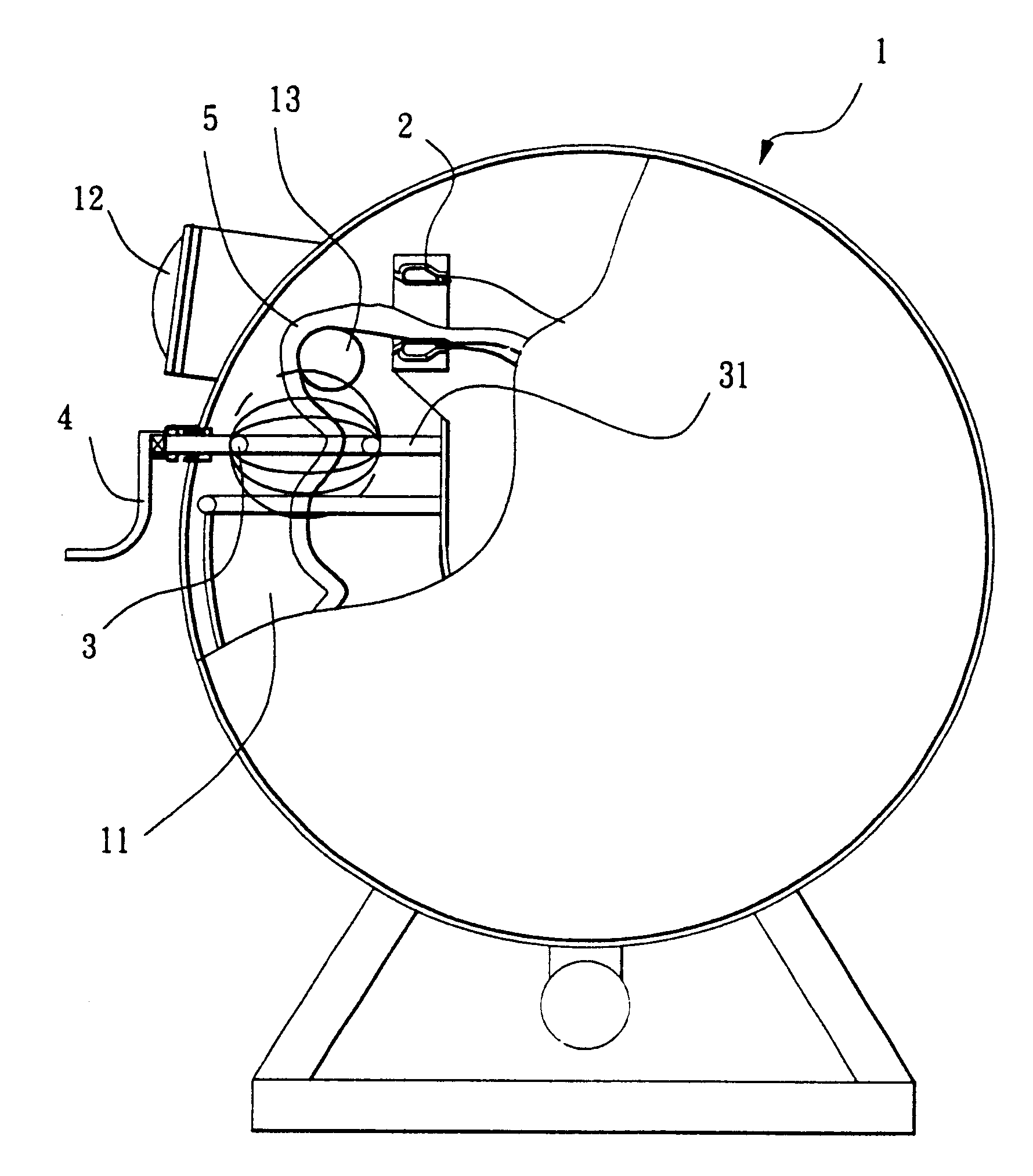
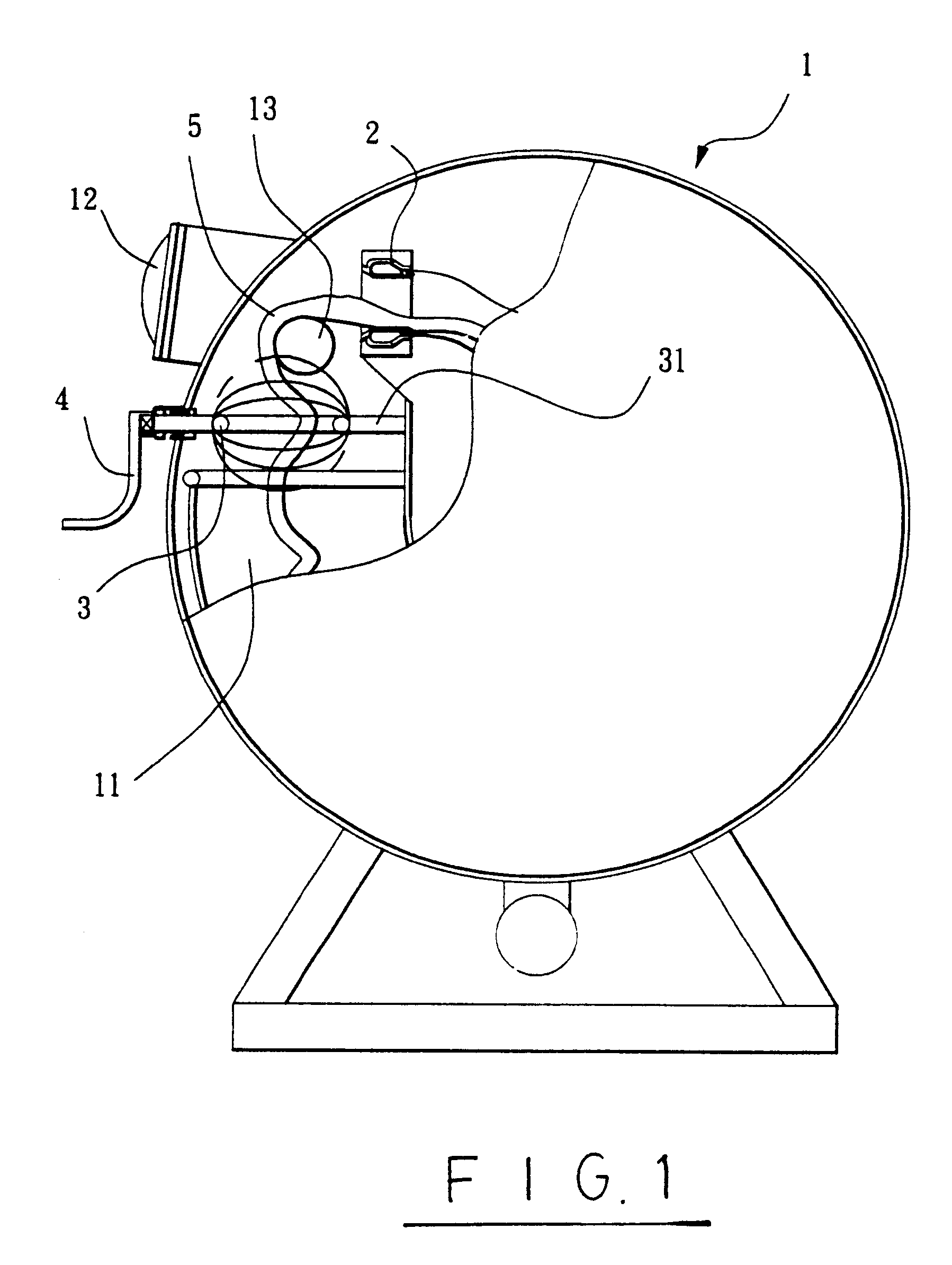
It is one object of the present invention to provide a fabric guide arrangement for a dyeing machine, which has fabric guide means to guide circulation of respective fabrics through respective dyeing vats. It is another object of the present invention to provide a fabric guide arrangement for a dyeing machine, which has means for enabling respective fabric guide means to be respectively adjusted to change the tension of respective fabrics subject to the thickness of respective fabrics. To achieve these and other objects of the present invention, there is provided a dyeing machine fabric guide arrangement comprising a plurality of shafts respectively installed in the housing of a dyeing machine above a respective dye vat in the housing, a plurality of fabric guide rings respectively fixedly mounted on the shafts inside the housing for guiding a respective fabric through a respective dye vat in the housing, and a plurality of hand wheels respectively fixedly fastened to the shafts outside the housing for enabling the operator to rotate the shafts and to change the angular position of the fabric guide rings respectively, so as to further adjust the tension of the respective fabrics passing through the fabric guide rings.

Problems solved by technology

However, because the fabric guide rings have a fixed size, they cannot fit different fabrics having different thickness.

Method used


Image

  • Dyeing machine fabric guide arrangement
  • Dyeing machine fabric guide arrangement
  • Dyeing machine fabric guide arrangement

Examples


Embodiment Construction

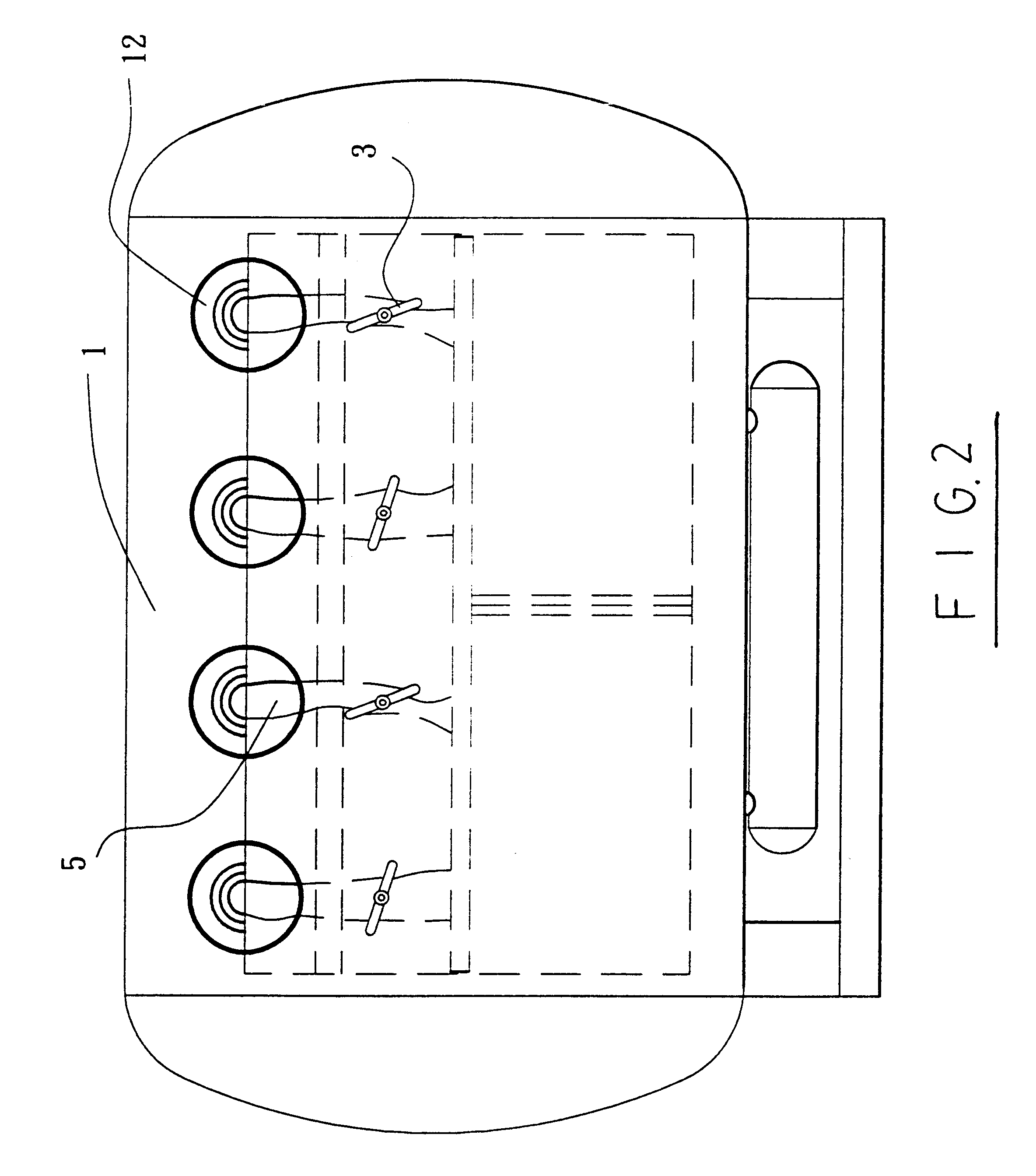
Referring to FIGS. from 1 through 5, a dyeing machine is shown comprising a housing 1 defining a plurality of dye vats 11 (which can be shaped like a trough or tube), a fabric guide roll 13 horizontally mounted inside the housing 1 above the dye vats 11, a plurality of spray nozzles 2 respectively disposed inside housing 1 above the dye vats 11 and controlled to spray a dyeing liquor toward the fabrics 5 passing through the dye vats 11, a plurality of visual windows 12 at the front side of the housing 1 near the top corresponding to the dye vats 11, a plurality of shafts 31 suspended above the dye vats 11 below the fabric guide roll 13 and respectively extended out of the front side of the dyeing machine 1 below the operation door 12, a plurality of fabric guide rings 3 respectively mounted on the shafts 31 inside the housing 1, and a plurality of hand wheels 4 respectively fastened to the shafts 31 outside the housing 1. The connection area between the front side of the housing 1 a...


PUM


Abstract

A dyeing machine fabric guide arrangement having a plurality of shafts respectively installed in the housing of a dyeing machine above a respective dye vat, a plurality of fabric guide rings respectively mounted on the shafts for guiding a respective fabric through a respective dye vat in the housing, and a plurality of hand wheels respectively fixedly fastened to the shafts outside the housing for enabling the operator to rotate the shafts and to change the angular position of the fabric guide rings respectively, so as to further adjust the tension of the respective fabrics passing through the fabric guide rings.

Description

BACKGROUND OF THE INVENTIONThe present invention relates to a dyeing machine, and specifically to a dyeing machine fabric guide arrangement, in which angular-adjustable fabric guide rings are provided to guide fabrics through a respective dyeing vat, and respectively turned to a respective angular position to adjust the tension of the respective fabrics subject to their thickness.In a dyeing machine, fabrics are continuously moved through respective dyeing vats, and dyeing liquor is driven out of spray nozzles toward fabrics, enabling moving fabrics to be well dyed in the respective dyeing vats. In order to keep smooth circulation of fabrics through the respective dyeing vats, fabric guide rings are commonly used and fixedly installed in the dyeing machine to guide respective fabrics. In order to achieve a satisfactory dyeing effect, fabrics of different thickness require different tension when passing through the respective dyeing vats. However, because the fabric guide rings have ...

Claims


Application Information

Patent Timeline
IPC IPC(8): D06B3/24D06B3/00
CPCD06B3/24
Inventor CHANG
Owner CHANG CHI LUNG
Learn More