
Grout pumps, control boxes and applicator tools, and methods for using the same

Inactive Publication Date: 2002-05-07
MUDMASTER
View PDF39 Cites 48 Cited by
  • Summary
  • Abstract
  • Description
  • Claims
  • Application Information

AI Technical Summary

Benefits of technology

It is a further object of some embodiments of the inventions to provide a handtool control box which may be used to apply grout to a work surface smoothly and in desired quantities.

Problems solved by technology

A particular problem faced by the drywall worker is how to apply a desired quantity of grout to a drywall blemish in a controlled manner, from a device that is maneuverable and efficient to use.

Method used


Image

  • Grout pumps, control boxes and applicator tools, and methods for using the same
  • Grout pumps, control boxes and applicator tools, and methods for using the same
  • Grout pumps, control boxes and applicator tools, and methods for using the same

Examples


Embodiment Construction

Below, one embodiment of the inventive concepts is described.

Slurry Pump System

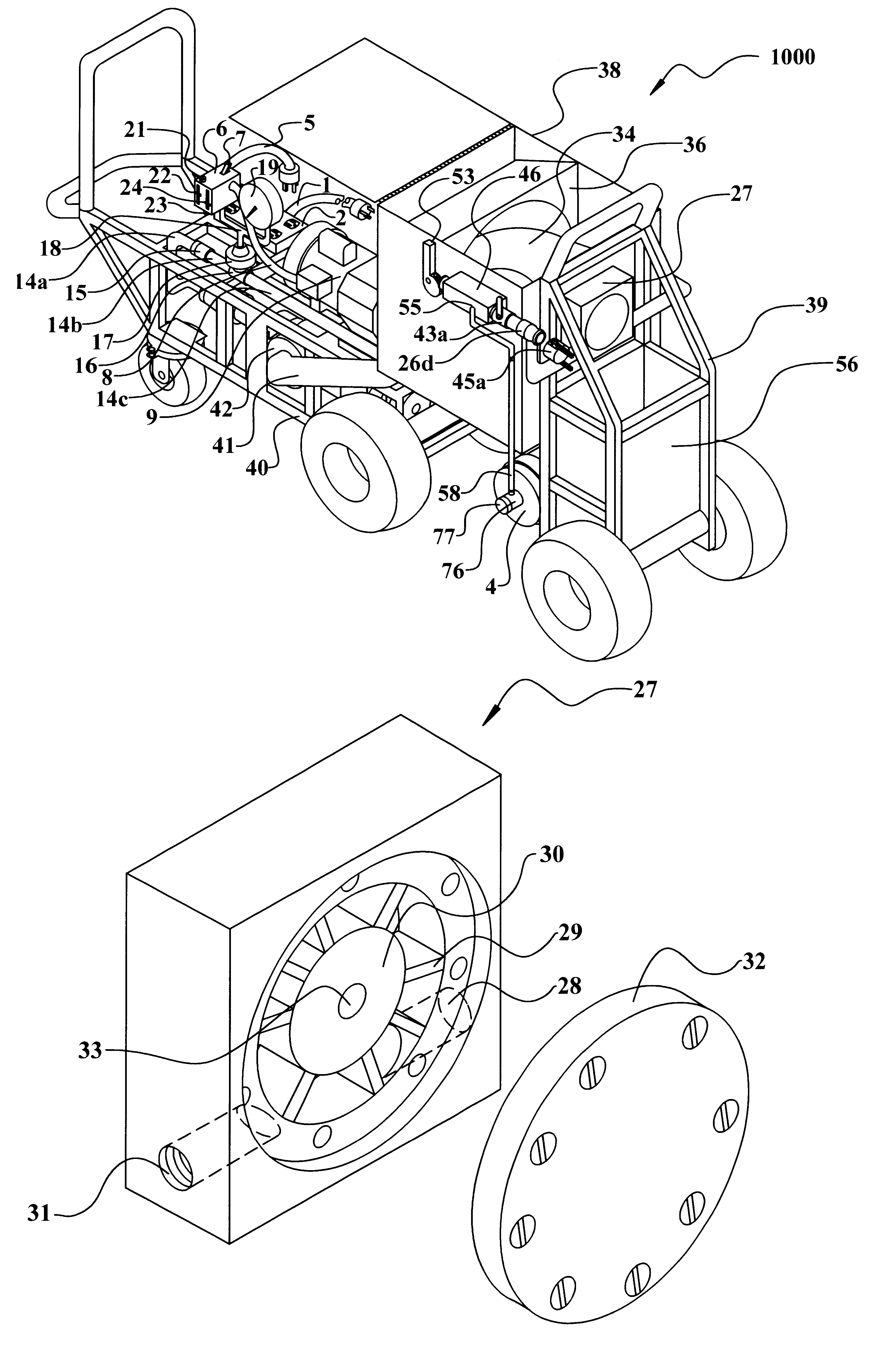
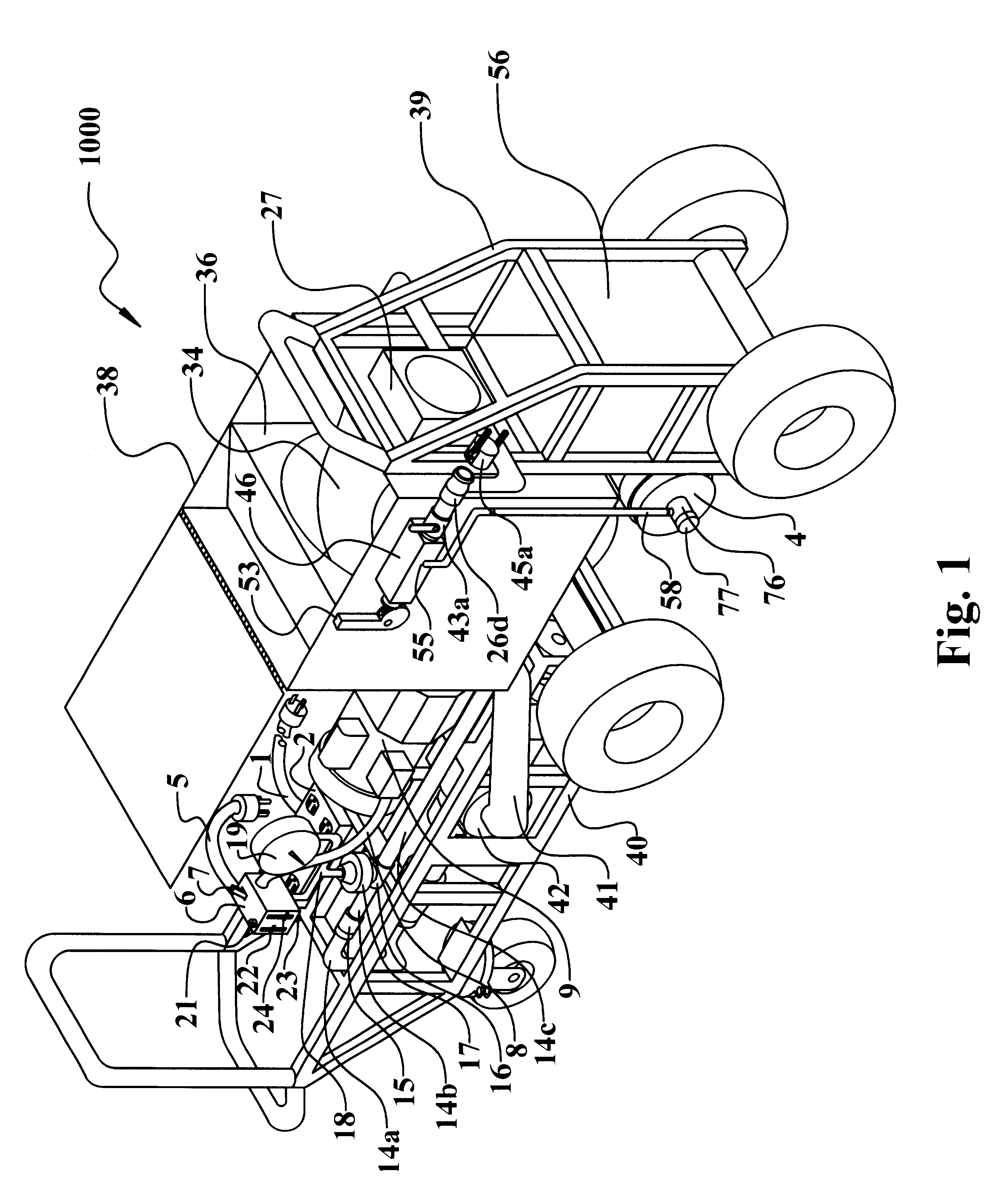
FIG. 1 depicts an automatic pump slurry system 1000 on a portable dolly 40. Main power cord 1 provides electricity to main power block 2 from which water pump cord 3 (FIG. 3) receives power for the water pump 4. The water pump 4 is depicted in FIG. 3 as well. The water pump 4 is pressure activated and turns on and off as needed to provide water to the system in order to keep the grout at a desired consistency.

A pressure sensor switch 6 is provided to keep the grout within the system pressurized so that the system is capable of providing grout to a remote location. Slurry sensor switch cord 5 plugs into the main power block 2 to receive electricity and provide it to slurry sensor switch 6. The toggle 7 of the pressure sensor switch is used to power the unit up for use and power it down for storage.

Referring to FIGS. 1, 5, 5a and 5b, when the slurry sensor switch 6 is turned on, it sends power through the m...


PUM


Abstract

A grout slurry pumping system, and a grout slurry control box and associated tools are described. Methods of using the pumping system and control box are also described. The pumping system and control box may be used separately or together. The pumping system maintains a grout slurry of desired consistency and can provide it through a hose to remote locations. The control box operates to apply grout to a work surface in desired quantities and in desired amounts according to a control valve.

Description

A. Field of the InventionsThe inventions relate to the field of pumps for pumping a slurry of grout to a remote location, tools for use at the remote location on a work surface. The inventions also related to control boxes and tools used for applying grout to a work surface in a controlled fashion. The inventions also relate to methods for accomplishing the foregoing.B. Prior ArtThere has been significant, but so far unsuccessful, effort in the prior art to construct group pumps, grout delivery systems, and grout applicator tools which provide for smooth and even application of grout to a construction surface. However, some of the prior art attempts to address the problem have yielded systems which either much be recharged with grout very frequently, thereby imposing a significant amount of down time and walking on the worker. Other prior art systems provide a continuous but uncontrollable flow of grout to the applicator tool, thus often oversupplying or undersupplying grout to the ...

Claims


Application Information

Patent Timeline
IPC IPC(8): E04F21/08E04F21/24E04F21/02E04F21/00
CPCE04F21/00E04F21/08E04F21/24E04F21/165Y10S417/90E04F21/026E04F21/1657E04F21/241
Inventor LEWIS, DARRIN WAYNEMARROTT, ROBERT A.
Owner MUDMASTER
Features
  • Generate Ideas
  • Intellectual Property
  • Life Sciences
  • Materials
  • Tech Scout
  • Unparalleled Data Quality
  • Higher Quality Content
  • 60% Fewer Hallucinations
Learn More