Fitting detecting connector

Inactive Publication Date: 2002-05-07
SUMITOMO WIRING SYST LTD
View PDF4 Cites 25 Cited by
  • Summary
  • Abstract
  • Description
  • Claims
  • Application Information

AI Technical Summary

Benefits of technology

The present invention responds to the above shortcoming, and aims to present a fitting detecting connector in which the locking arm returns smoothly to its original position when the two connector housings have been correctly fitted together.

Problems solved by technology

However, as shown in FIG. 20, when the locking arm d rises over the stopping protrusion b and returns to its original position, the resilient spring force of the coiled springs f is sometimes exerted from the restraining wall g of the spring holder e towards the tip of the locking arm d, as shown by the arrow in FIG. 20, thus regulating the return of the locking arm d. That is, there is the possibility that locking cannot occur even though the two housings a and c have been correctly fitted together, and thus further improvement is required.

Method used


Image

  • Fitting detecting connector
  • Fitting detecting connector
  • Fitting detecting connector

Examples


first embodiment

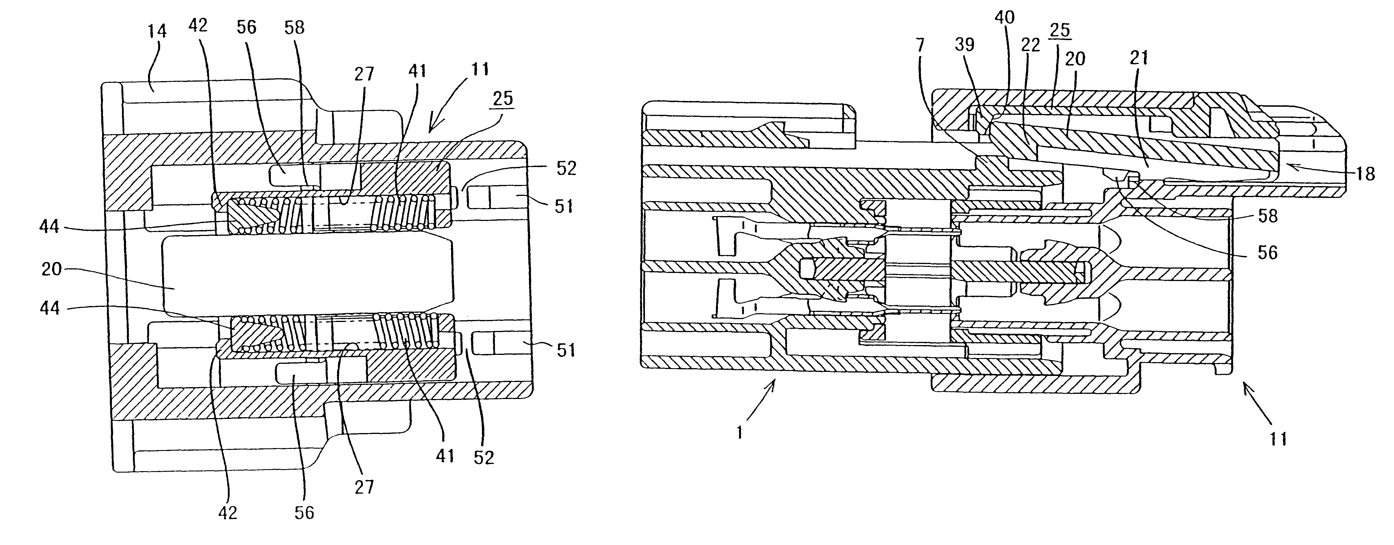
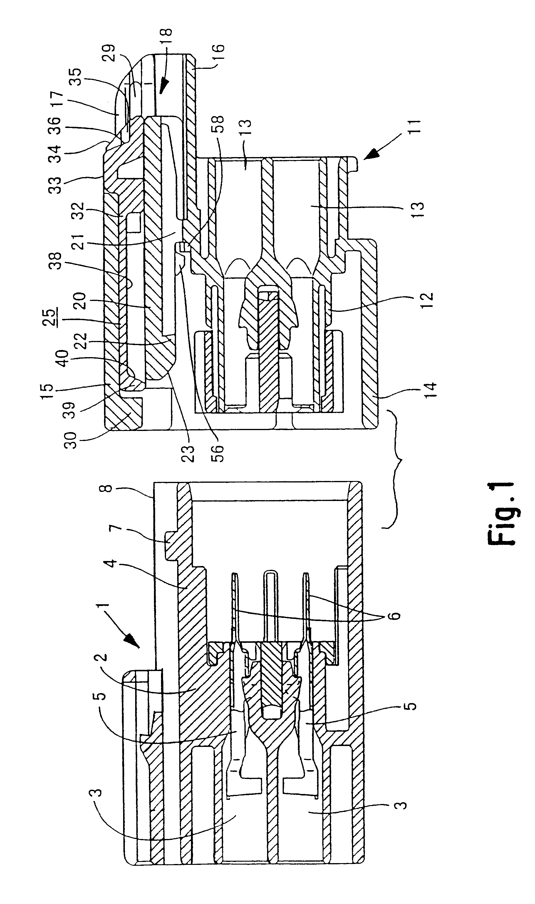
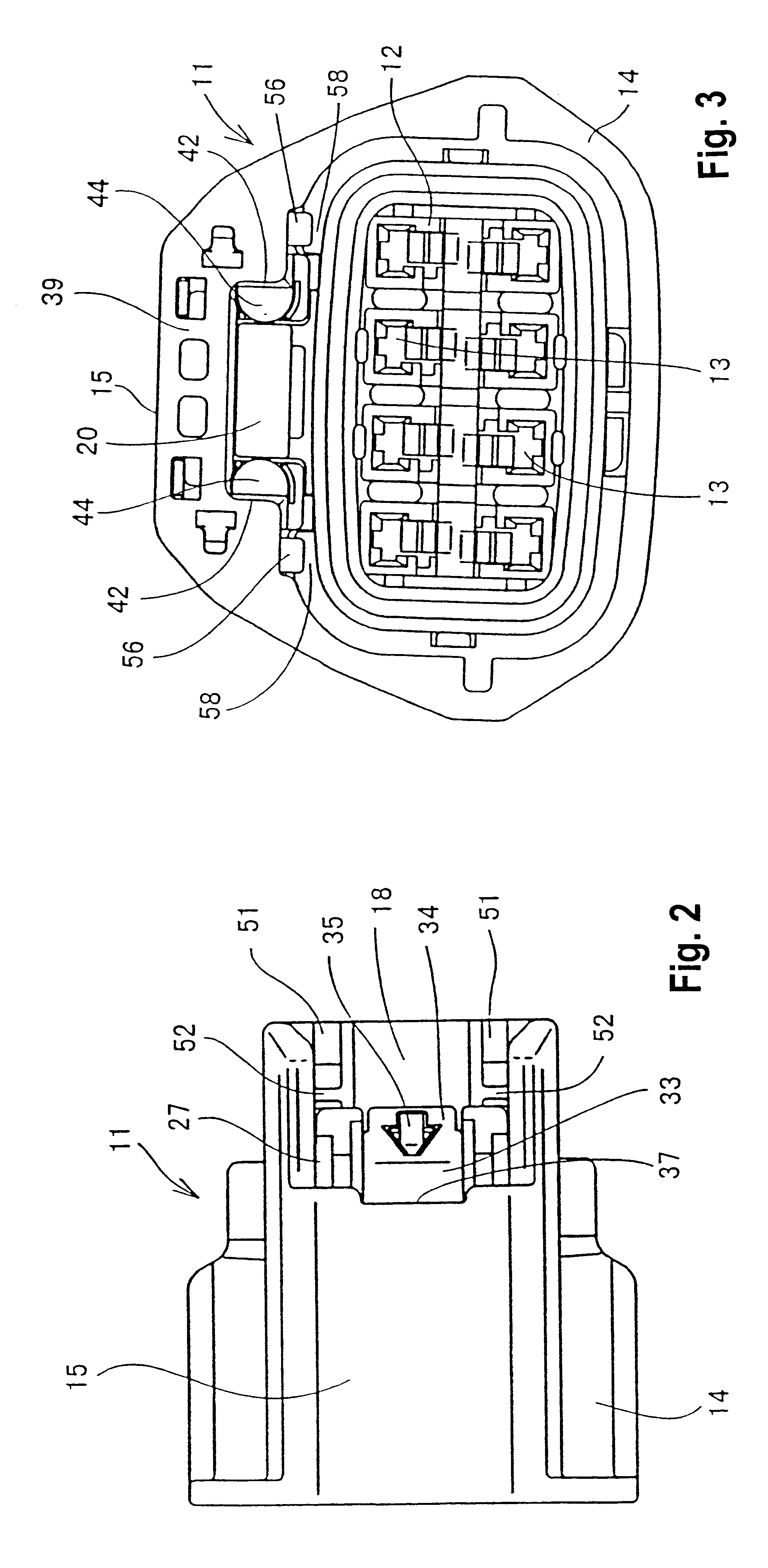
the present invention is described below with the aid of FIGS. 1 to 16. As FIG. 1 shows, this embodiment is provided with a male connector housing 1 (hereafter referred to as male housing) fitting with a female connector housing 11 (hereafter referred to as female housing). Mutually fitting faces of the housings 1 and 11 will be considered to be anterior faces.

The male housing 1 is made from plastic and is part of an electrical apparatus (not shown). Eight cavities 3 are formed as two upper and lower layers in a main member 2 of the male housing 1, and a tubular fitting cylinder 4 is formed on an anterior face of the main member 2. Male terminal fittings 5 are inserted into each cavity 3, tabs 6 of these male terminal fittings 5 protruding into the fitting cylinder 4 and being housed therein in a state that prevents removal. A stopping protrusion 7 is formed on an upper face of the fitting cylinder 4 at a location close to an anterior edge thereof which faces the female connector ho...


PUM


Abstract

A spring holder 25 containing coiled springs 41 is installed in a female housing 11. When a male housing 1 and this female housing 11 are fitted together, a locking arm 20 rises over a stopping protrusion 7, a restraining wall 39 simultaneously engages a locking claw 22, and the coiled springs are compressed. The locking claw 22 makes contact with a contacting face of the restraining wall 39, this contacting face being a tapered face 40. When the locking arm 20 is about to pass over the stopping protrusion 7 to return to its original position, the restraining wall 39 receives a spring force F from the coiled springs and pushes the locking arm 20. A component force F1 in a returning direction of the locking arm 20 is obtained from this spring force F due to the tapered face 40. The component force F1 and the returning force of the locking arm 20 itself cause the locking arm 20 to return smoothly, and the locking arm 20 thus engages with the stopping protrusion 7.

Description

The present invention relates to a fitting detecting connector.BACKGROUND TO THE INVENTIONDisclosed in JP-9-211020 is a fitting detecting connector in which, when male and female connector housings are not correctly fitted together, force from a spring pushes the housings apart, and in which a locking arm is provided on one of the connector housings, this locking arm maintaining the two connector housings and the spring in a fitted state.The configuration of this fitting detecting connector is explained briefly below with the aid of FIG. 19. A male housing a fitting together with a female housing c has a stopping protrusion b. The corresponding female housing c has a bendable locking arm d for engagement by the stopping protrusion b and a spring holder e capable of being moved in an anterior-posterior direction. Coiled springs f are housed within this spring holder e, these coiled springs f being compressed by an anterior edge of the male housing a. When the two housings a and c are...

Claims


Application Information

Patent Timeline
Patent Type & Authority Patents(United States)
IPC IPC(8): H01R13/64H01R13/641H01R13/627H01R13/639H01R24/00
CPCH01R13/641H01R13/6272
Inventor KAWASE, HAJIMENISHIDE, SATORUISHIKAWA, RYOTARO
Owner SUMITOMO WIRING SYST LTD
Why Eureka
Try Eureka