Method for rendering shadows using a shadow volume and a stencil buffer

Inactive Publication Date: 2002-05-07
CREATIVE TECH CORP
View PDF11 Cites 92 Cited by
  • Summary
  • Abstract
  • Description
  • Claims
  • Application Information

AI Technical Summary

Problems solved by technology

A problem with the prior art technique occurs when the viewpoint is within the shadow volume, or, more generally, when the shadow volume intersects the near cl

Method used


Image

  • Method for rendering shadows using a shadow volume and a stencil buffer
  • Method for rendering shadows using a shadow volume and a stencil buffer
  • Method for rendering shadows using a shadow volume and a stencil buffer

Examples


Embodiment Construction

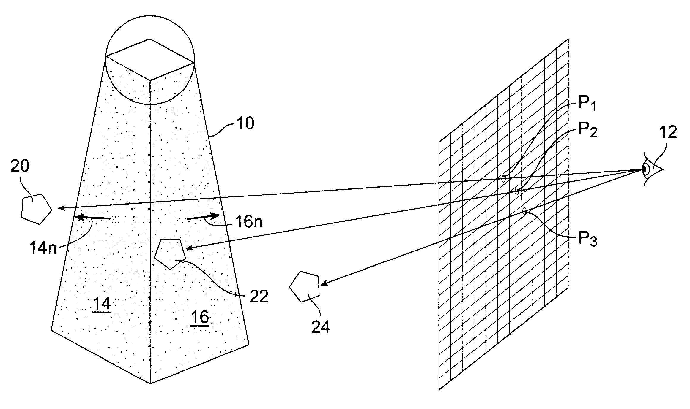
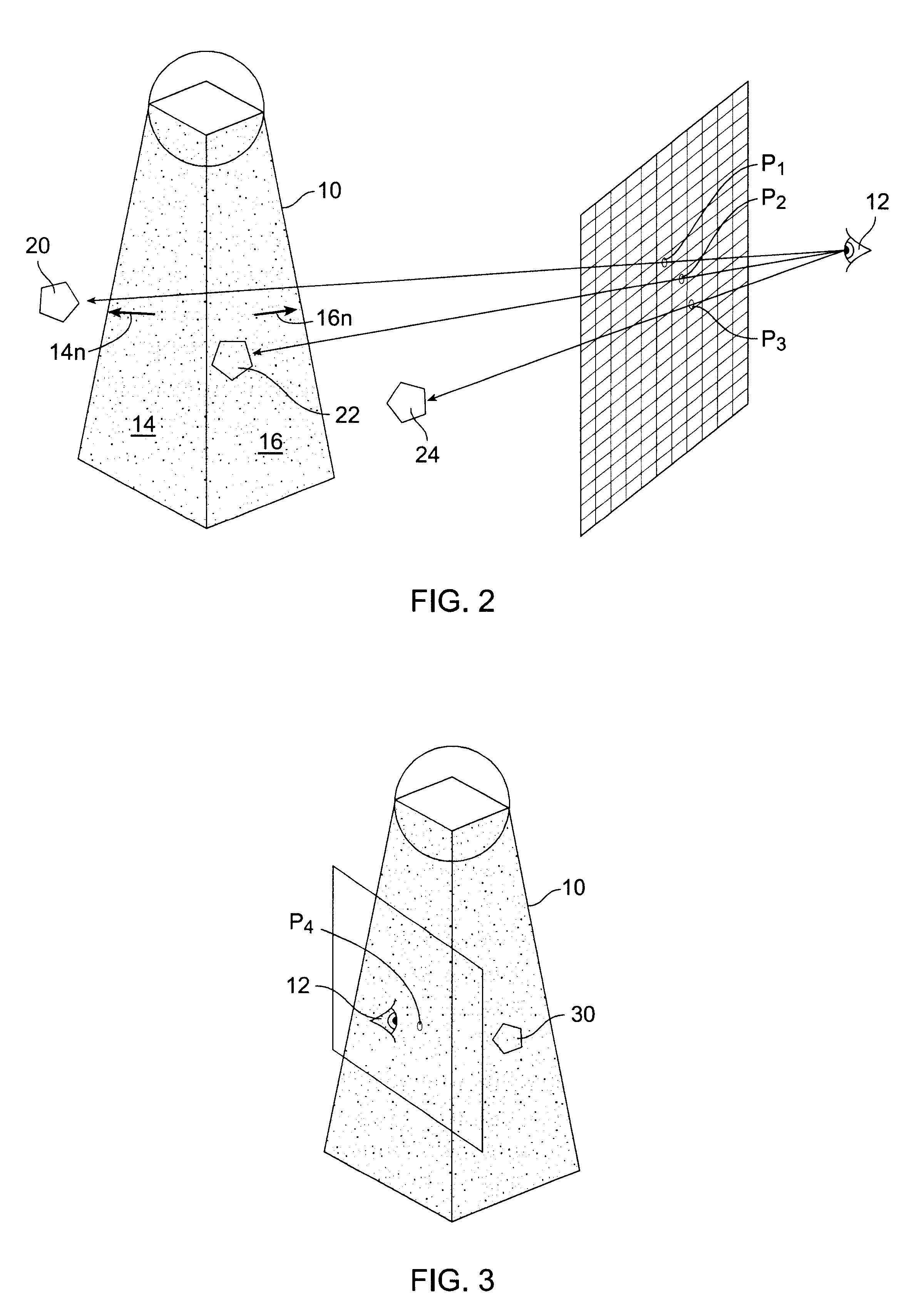
A preferred embodiment of the present shadow rendering process will be described with reference to the following pseudo-code and FIG. 2.

A key step in the present process is the definition of the newZTest (X, P) function which inverts the z-test comparison used in the prior art. In the usual test, pixels having depth (z) values less than the depth (z) values stored in the z-buffer pass the z-test. In newZTest( ), pixels having depth (z) values greater than the corresponding depth (z) value stored z-buffer values pass the new z-test.

Steps A and B are similar to the prior art, the polygons in the scene are drawn and z-buffer values for the scene are stored. newztest( ) is enabled and z-write is disabled.

In step C, the all bits in the stencil buffer are reset to initialize the buffer. As will be apparent below, there is no need to set the stencil bits in the case where the viewpoint is within the shadow volume.

In step D, the back-facing shadow volume polygons are drawn. This reverses th...


PUM


Abstract

A method for real-time shadow rendering in a 3-D graphics scene uses an inverted z-test to mark a shadow area in a stencil buffer. Front and back facing shadow volume polygons are rendered subsequent to rendering the scene and corresponding stencil buffer entries are incremented for pixels viewing the back facing polygon when the new z-test is passed and decremented for pixels viewing the front facing polygons when the new z-test is passed. The new z-test is passed for pixels having depth (z) values greater than the corresponding depth value stored z-buffer.

Description

1. Field of the InventionThe present invention relates to 3-D computer graphics and more particular to rendering shadows cast by objects in a 3-D scene.2. Description of the Relevant ArtRealistic 3-D rendering of a scene requires rendering shadows cast by objects in the scene. The importance of shadow in locating an object relative to a plane is depicted in FIGS. 1A and 1B. Note that in FIG. 1A it is not clear whether the sphere is touching the plane while in FIG. B the rendering of the shadow makes the relationship clear.For static scenes shadows can be rendered using a ray casting procedure. However, for animation, such as utilized in 3-D computer games, shadows must be rendered in real time. Shadows create dramatic effects in games, for example making monsters look more sinister. Additionally, if a game is played by multiple players, shadows enhance the game quality because opponents may be able to see a shadow before the actual game character appears on the screen.One real-time ...

Claims


Application Information

Patent Timeline
IPC IPC(8): G06T15/40G06T15/10G06T15/50G06T15/60
CPCG06T15/60G06T15/405
Inventor BILODEAU, WILLIAMSONGY, MICHAEL
Owner CREATIVE TECH CORP
Why Eureka
Try Eureka