
Shadow production method and device for adjustment shadow space arithmetic

A spatial algorithm and shadow technology, applied in computing, 3D image processing, image data processing, etc., can solve the problems of computing cost and updating template buffer bandwidth, etc.

Active Publication Date: 2006-02-22
VIA TECH INC
View PDF0 Cites 1 Cited by
  • Summary
  • Abstract
  • Description
  • Claims
  • Application Information

AI Technical Summary

Problems solved by technology

In the application, one of the depth pass algorithm and the depth fail algorithm is generally selected, so the operation cost and the bandwidth of updating the stencil buffer can easily become very large due to different viewing angles, so a solution is needed , to operate with a suitable depth test

Method used


Image

  • Shadow production method and device for adjustment shadow space arithmetic
  • Shadow production method and device for adjustment shadow space arithmetic
  • Shadow production method and device for adjustment shadow space arithmetic

Examples


Embodiment Construction

[0031]The direction of the present invention discussed here is a shadow generation device and method of an adaptive shadow space algorithm. In order that the present invention can be thoroughly understood, the detailed construction will be set forth in the following description. Obviously, the practice of the invention is not restricted to specific details familiar to those skilled in lighting devices. In other instances, well-known compositions or process steps have not been described in detail in order to avoid unnecessarily limiting the invention. The preferred embodiments of the present invention will be described in detail as follows, but in addition to these detailed descriptions, the present invention can also be widely implemented in other embodiments, and the scope of the present invention is not limited, and the following scope of the invention is allow.

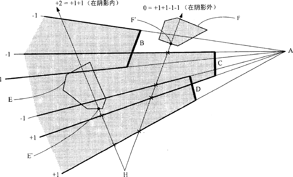
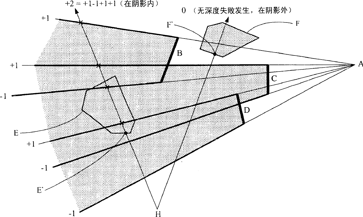
[0032] The shadow volume algorithm includes depth pass (Z pass) algorithm and depth fail (Z fail) algorithm. ...


PUM


Abstract

This invention discloses one shade generation method and device by adapting shade space, wherein, when rendering one frame shadow volume, the statistics deep deduces the number of z fail through z pass to compute the graph effect. So it can make the next frame shallow space formula according to the next best.

Description

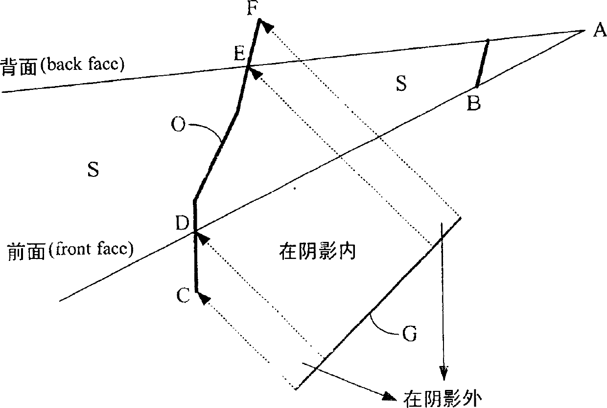
technical field [0001] The present invention relates to a shadow space calculation method and device, in particular to a shadow space calculation method and device capable of adaptively using a depth pass algorithm and a depth fail algorithm. Background technique [0002] In a 3D graphics system, additional techniques are required to describe shadows. Simply put, it is to find out those pixels in the shadows. These techniques include shadow volume, shadow mapping, etc. Wait. [0003] The shadow space method mainly defines the space covered by the shadow as a shadow space to determine which parts of the screen are located in the shadow space. As shown in Figure 1A, assuming that the light is irradiated by the light source A, and the shade B is blocked in it, so the range where the light is shaded by the shade B is the shadow space S, and the shadow space S can be divided into front face and back face (back face) to define. When an object O on the screen is to be projected ...

Claims


Application Information

Patent Timeline
Patent Type & Authority Applications(China)
IPC IPC(8): G06T15/60
Inventor 李润容彭绍贞
Owner VIA TECH INC
Learn More