Optical target and apparatus and method for automatic identification thereof

a target and automatic identification technology, applied in the field of optical target and automatic identification of apparatus, can solve the problems of inability to dynamically measure the velocity of target or object, slow down the measurement process, and inability to achieve dynamic measurements of target or object velocity for fast moving objects

Inactive Publication Date: 2002-05-07
BAE SYSTEMS PLC
View PDF8 Cites 37 Cited by
  • Summary
  • Abstract
  • Description
  • Claims
  • Application Information

AI Technical Summary

Problems solved by technology

Although these schemes enable adequate identification of optical targets, the processing involved can be inefficient and can thus slow dow...

Method used


Image

  • Optical target and apparatus and method for automatic identification thereof
  • Optical target and apparatus and method for automatic identification thereof
  • Optical target and apparatus and method for automatic identification thereof

Examples


Embodiment Construction

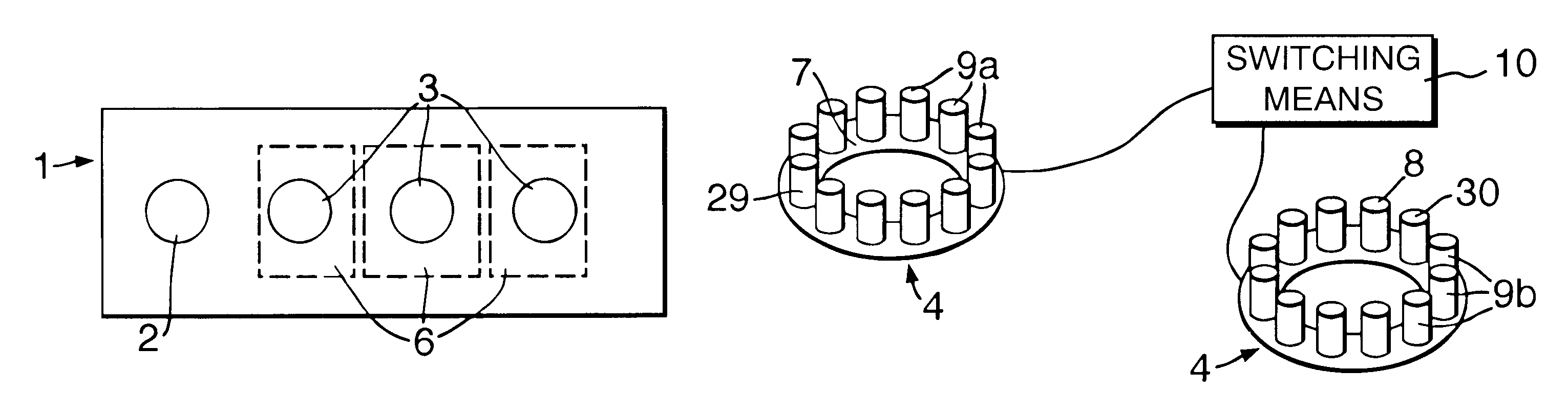
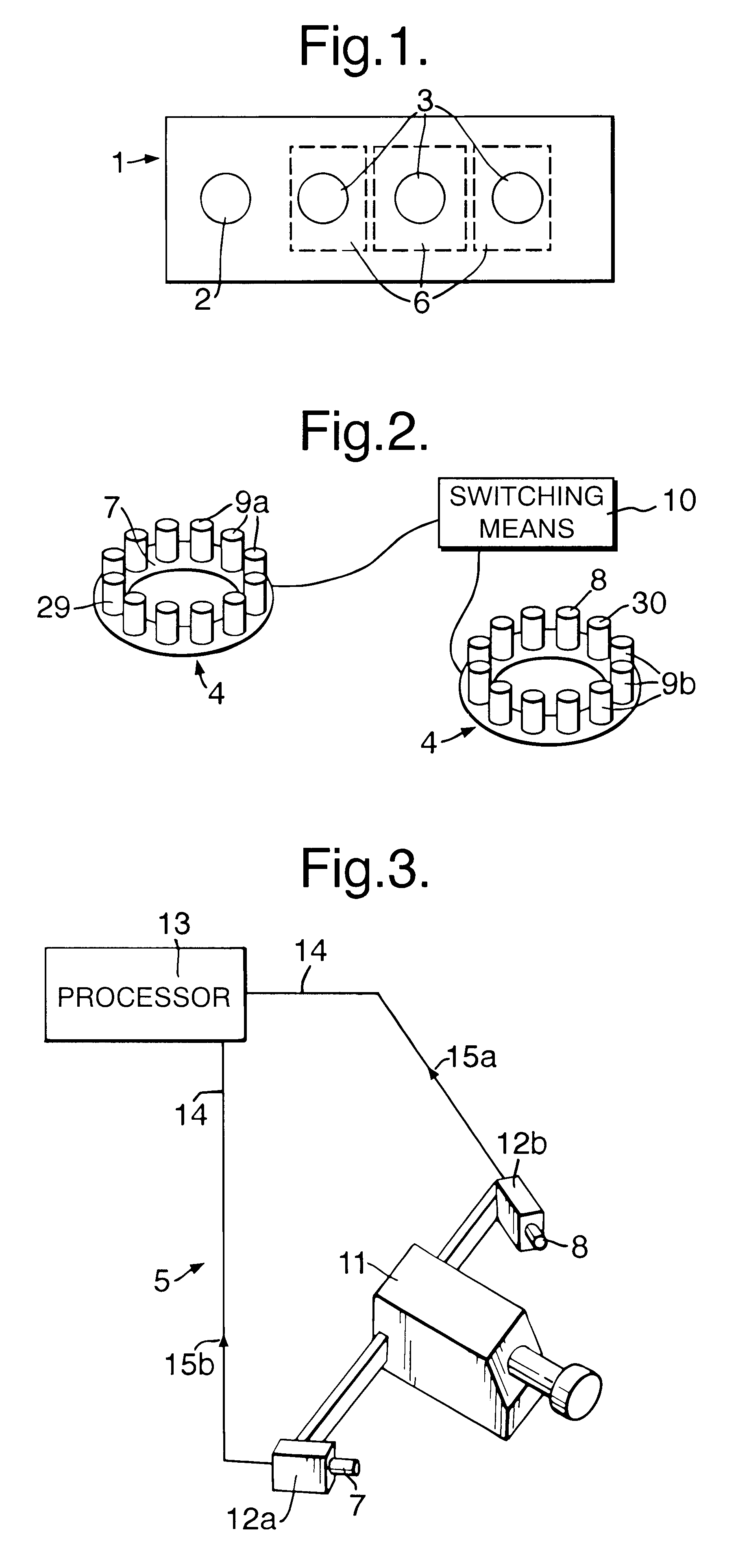
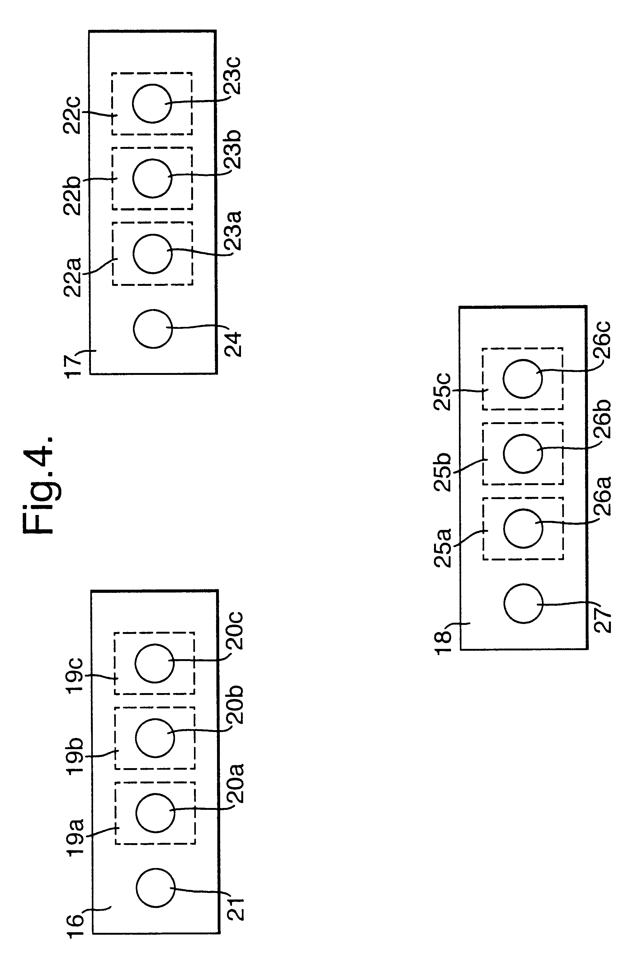
An optical target, and apparatus and method for automatic identification thereof according to the present invention, as shown in FIGS. 1 to 6 of the accompanying drawings, is intended for use in situations where multiple optical targets are affixed to an object, and in which more than one imaging device images the targets in order to measure a condition such as the position and orientation of the object. The accuracy of these measurements is dependent on, among other parameters, the correspondence of the targets between images recorded on said imaging devices, and the present invention accordingly provides a means of identifying targets by groupings of different coloured retro-reflective targets.

FIG. 1 of the accompanying drawings show an optical target 1, including a positioning sub target 2 for determining position and a plurality of identifying sub targets 3 for identifying one optical target 1 from another, each of which plurality of identifying sub targets 3 is a different colo...


PUM


Abstract

An optical target (1) including a positioning sub target (2) for determining position, and a plurality of identifying sub targets (3) for identifying one optical target (1) from another, each of which plurality of identifying sub targets (3) is a different color from the positioning sub target (2).

Description

1. Field of the InventionThis invention relates to an optical target and apparatus and method for automatic identification thereof, particularly, but not exclusively, suitable for photogrammetry measurement tasks.2. Discussion of Prior ArtPhotogrammetry systems use optical targets attached to an object of interest, and the photogrammetry system is able to determine the two dimensional and three dimensional locations of the targets in order to measure the dimensions of, or position of the object. It is often useful to assign a value or code to each of the targets so as to distinguish the targets from one another. The ability to identify specific targets has particular application in identifying specific objects, determining object orientations, matching measured points to computer aided design (CAD) data and denoting known or control target locations. These capabilities are important where photogrammetry systems are to be embedded in assembly processes and operations. Furthermore, if...

Claims


Application Information

Patent Timeline
IPC IPC(8): G01C11/06G01C15/02G01C11/00G01C15/06
CPCG01C15/02G01C11/06
Inventor GOOCH, RICHARD M
Owner BAE SYSTEMS PLC
Why Eureka
Try Eureka