Tool jig for doors

a door and tool technology, applied in the field of door tool jigs, can solve the problems of only satisfactory arrangement, added substantial cost to the job, and care that must be taken in accurately placing the holes

Inactive Publication Date: 2002-05-21
FRIDMAN YEVGENY
View PDF10 Cites 43 Cited by
  • Summary
  • Abstract
  • Description
  • Claims
  • Application Information

AI Technical Summary

Problems solved by technology

This arrangement is only satisfactory when all of the doors have their holes located at the same distance from the edge of the door.
One difficulty is that there are currently two "standard" locksets and the difference between them is that distance between the knob hole 12 and the edge of the door may be either one of two standard sizes, i. e., 2 inches or 21/2 inches.
Another problem ac

Method used


Image

  • Tool jig for doors
  • Tool jig for doors
  • Tool jig for doors

Examples


Embodiment Construction

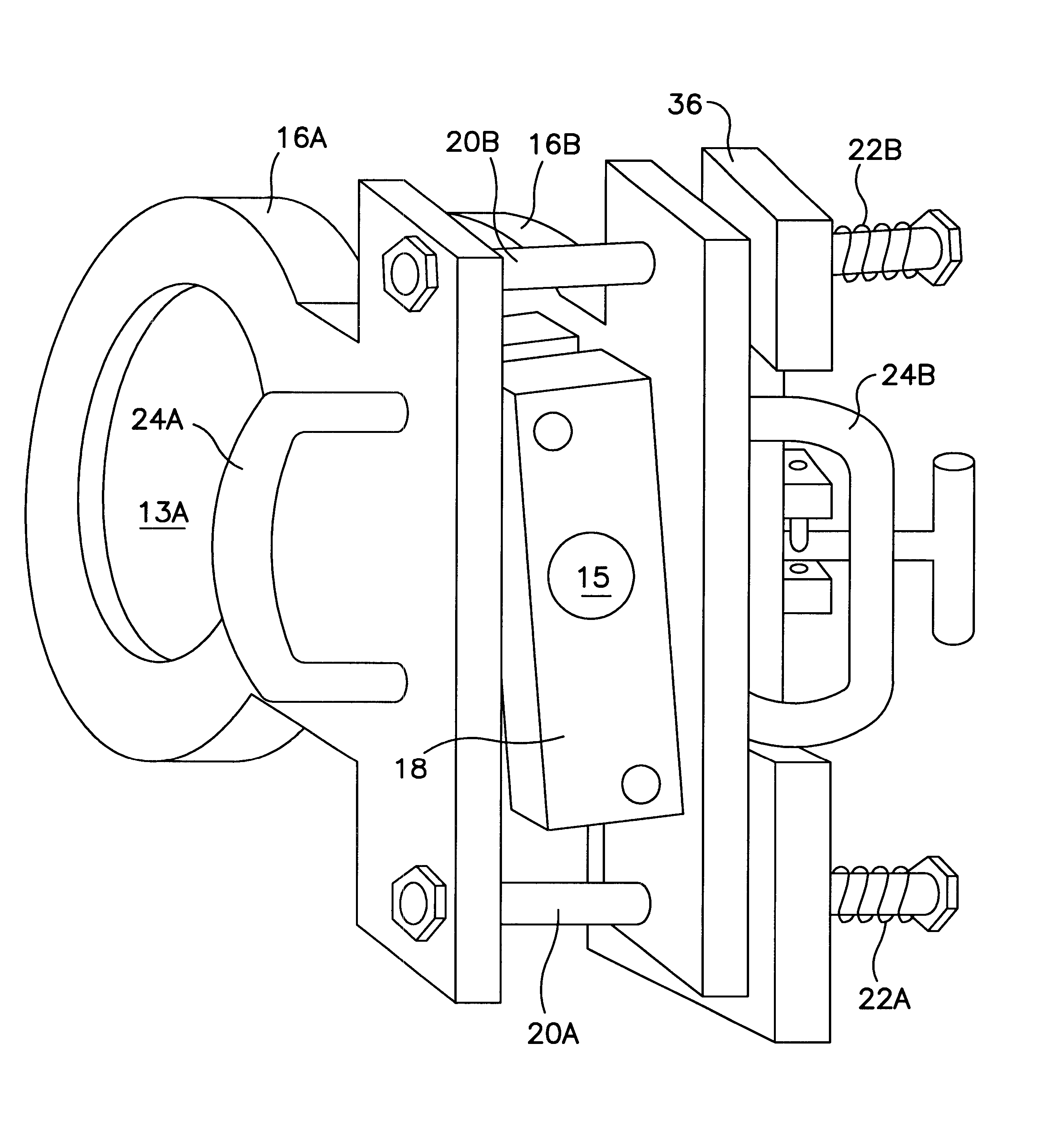
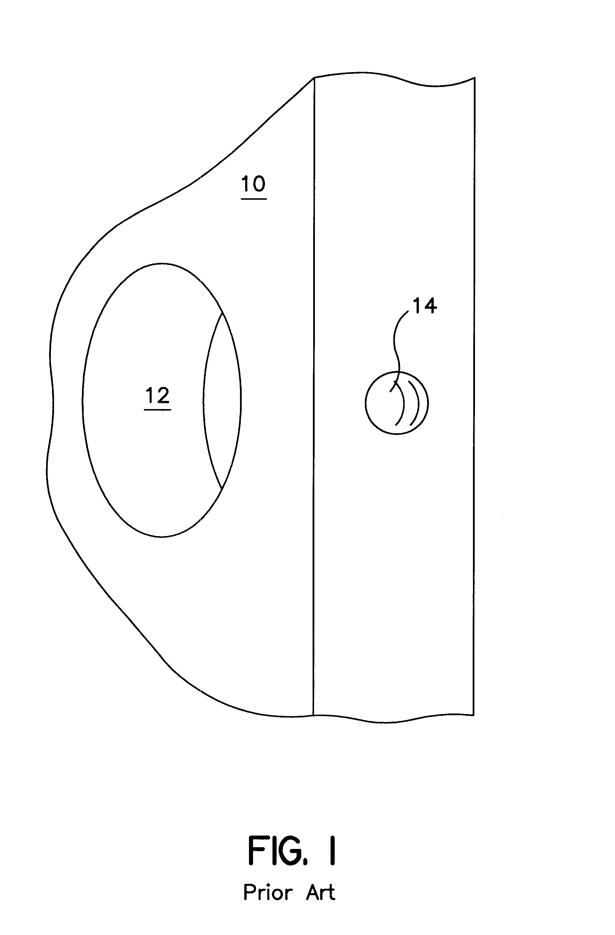
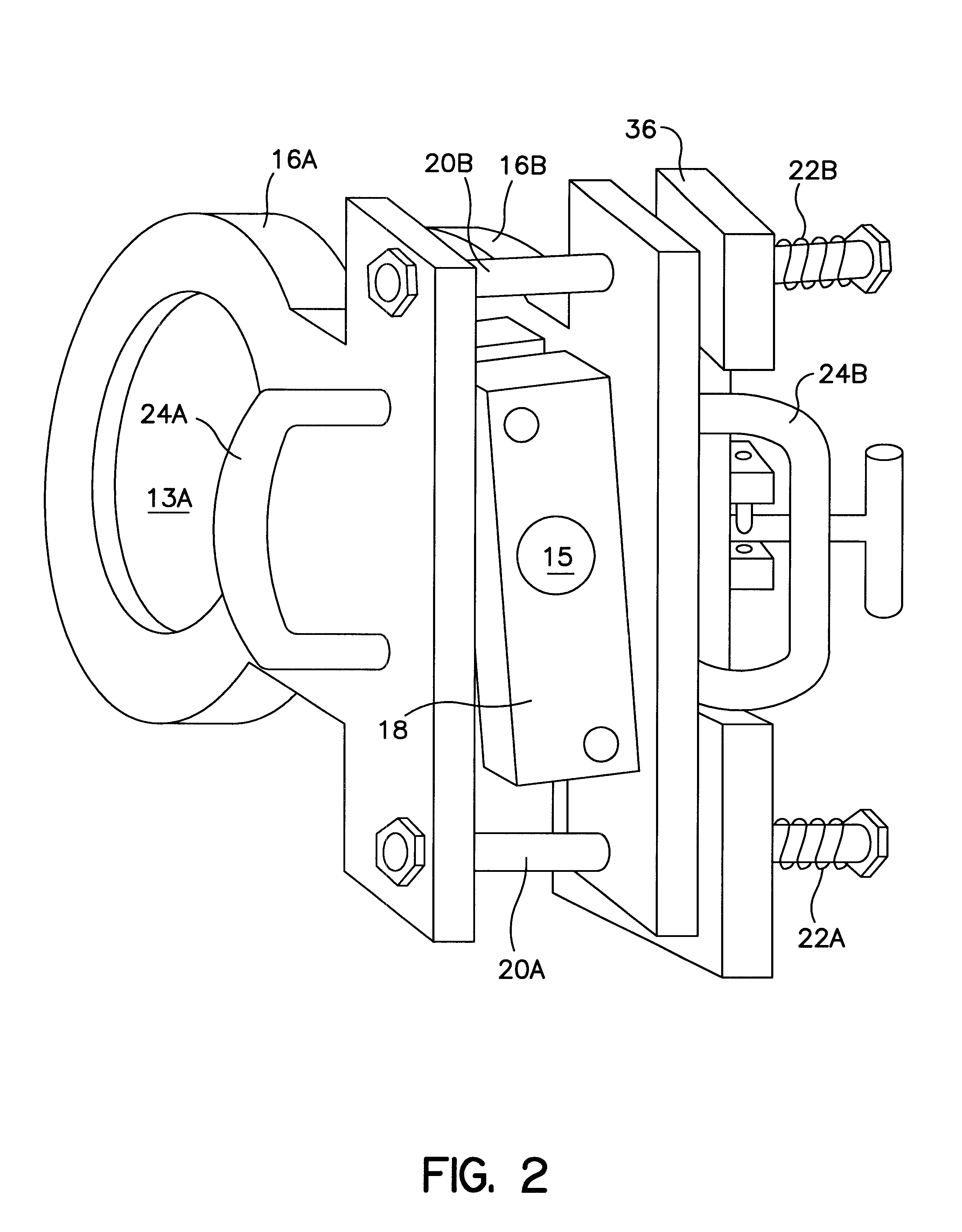
Turning now to a discussion of the drawings, FIG. 1 is an assembly view showing the tool jig clamp of this invention and FIG. 3 is an exploded view of FIG. 1. FIG. 4 is a side view showing a door 10 (in section) with knob hole 12 and lock hole 14 clamped between jaws 16A, 16B.

Jaws 16A, 16B have apertures 13A, B for guiding a hole saw to drill the knob hole 14 and have apertures 17A, B for slidable mounting on rods 20A and 20B. The jaws 16A, B are spring loaded by springs 22A, B to clamp a door 10 between jaws 16A, B as shown in FIG. 4.

A center block 18 is shown having the guide hole 15 for drilling the lock hole 14 in door 10. Ear 26A attached to jaw 16A slids into slot 34A of center block 18 and ear 26B attached to jaw 16B slides into slot 34B attached to jaw 16B of center block 18. Center block 18 has one end pivotally mounted to ear 26 A by pin 28A through apertures 30A an 32A and another end pivotally mounted to ear 26B by pin 28B through apertures 30B an 32B providing that, whe...


PUM

PropertyMeasurementUnit
Forceaaaaaaaaaa
Widthaaaaaaaaaa
Distanceaaaaaaaaaa

Abstract

A drill jig for a door comprising a pair of jaws that clamp onto the edge of a door. The clamp is first attached to the edge of the door by a spring load and then further secured by a cam which the workman turns to apply additional clamping force. A center block between the jaws has a guide hole for drilling the lock hole in the edge of the door. The centerline of the center block is perpendicular to the centerline of the knob hole and is positionable to permit location of the knob hole at either one of two locations depending on the style of the lock set. The center block is hingably attached to both jaws of the clamp such that guide hole for drilling the lock hole is always centered between the jaws.

Description

This invention is related to tool jigs for drilling holes and particularly to a tool jig that clamps onto the edge of a door providing a guide for the knob hole and the latch hole required for installing a lockset.BACKGROUND AND INFORMATION DISCLOSURECommon procedure for a builder to install a door is to order a door panel that has a standard size knob hole (hole through the door) for receiving the lockset. The hole is typically located near one long edge of the door 36 inches from the bottom edge. The hole is selected to accommoate any one of standard locksets. Installation of the lockset requires that a pattern of holes be drilled by the carpenter in the door proximal to the knob hole through which bolts are inserted to secure the lockset. The position and size of the smaller holes varies according to the lockset selected by the builder.Alignment of the holes with the edge of the door is very critical for the sake of appearance as well as for ease of installation of the lockset. C...

Claims


Application Information

Patent Timeline
IPC IPC(8): B23B49/00B23B47/28B23B49/02B23B47/00
CPCB23B47/287B23B49/023Y10T408/567Y10T408/563
Inventor FRIDMAN, YEVGENY
Owner FRIDMAN YEVGENY
Why Eureka
Try Eureka