Fuse stab connector for electronic modules

a technology of electronic modules and stab connectors, applied in the direction of electrical apparatus, incorrect coupling prevention, coupling device connection, etc., can solve the problems of unnecessarily duplicated connecting means and relatively high cos

Inactive Publication Date: 2002-05-28
SCHNEIDER ELECTRIC USA INC
View PDF5 Cites 14 Cited by
  • Summary
  • Abstract
  • Description
  • Claims
  • Application Information

AI Technical Summary

Benefits of technology

It is a further object of the present invention to provide a connector that eliminates duplication of expensive conductive components by combining the connective functions of fuses and modules.

Problems solved by technology

They also unnecessarily duplicate connecting means.
Stab connectors for conducting high currents for fuses and high currents and voltages for surge suppression, have high volumes of conductive metals which make them relatively expensive.

Method used


Image

  • Fuse stab connector for electronic modules
  • Fuse stab connector for electronic modules
  • Fuse stab connector for electronic modules

Examples


Embodiment Construction

Reference will now be made to the drawings wherein like structures will be provided with like reference numerals.

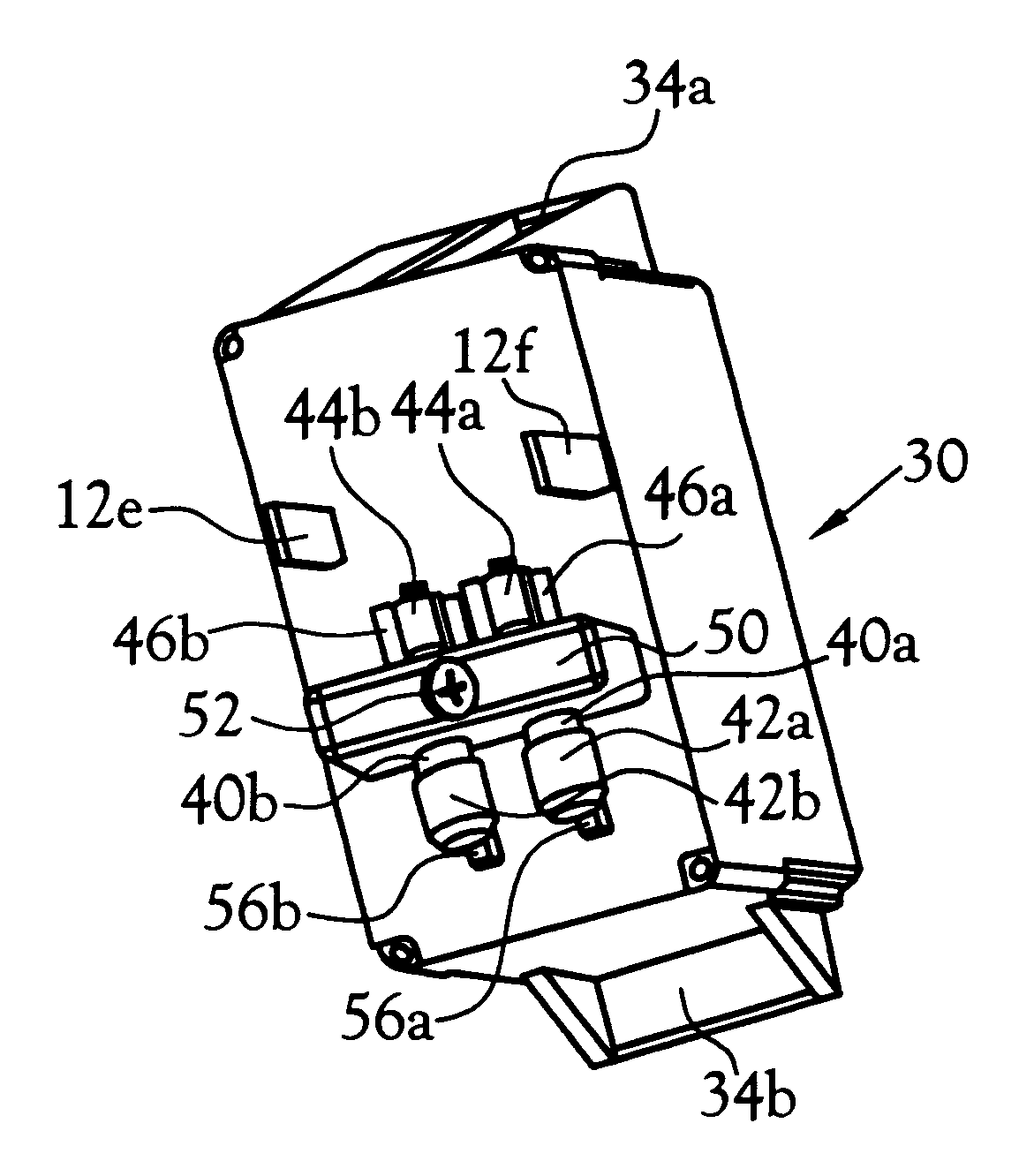
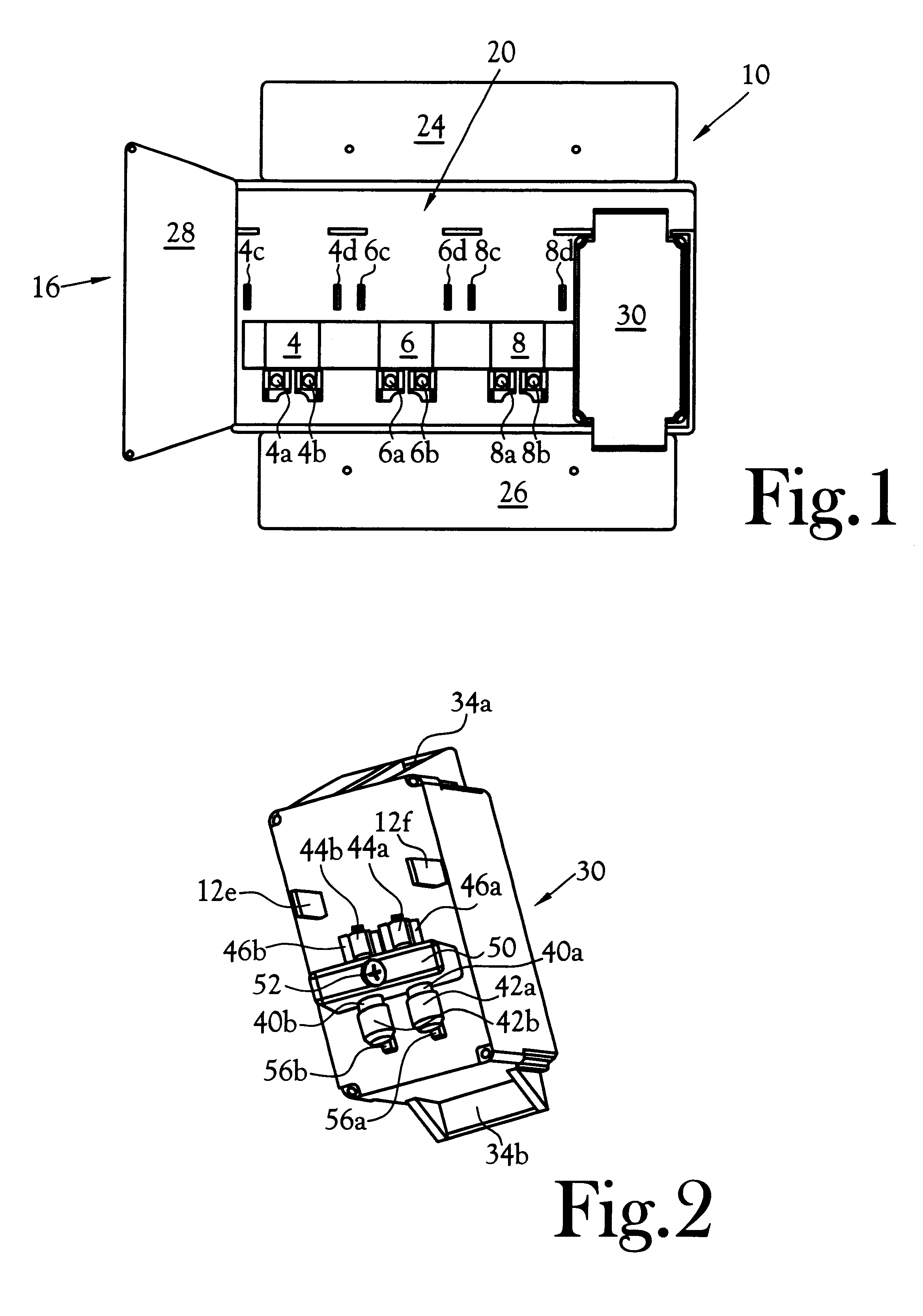
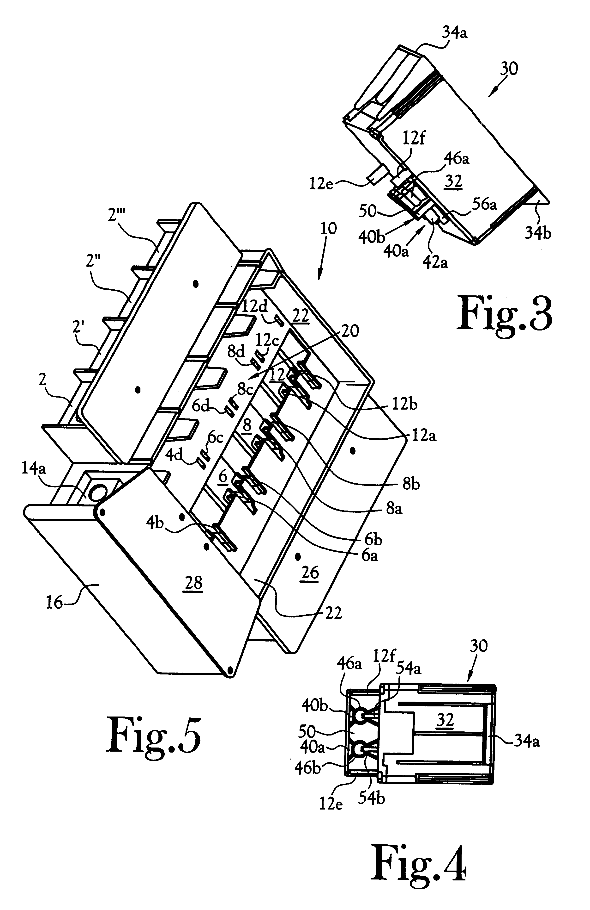
Referring to FIGS. 1 and 5, there is shown, generally designated at 10, a power distribution circuit box. The box has a well generally depicted at 20 in which surge suppression modules 30 (FIG. 1) can be placed. FIG. 1 depicts one such module 30 fixed in position in the well 20. Three more would normally be in place, but are not depicted so as to provide a view to underlying structure.

Line connectors for the power distribution lines are depicted at 2-2'" (FIG. 5). Opposing connectors for the other in / out lines (not in view) are opposite connectors 2-2'". In this system, these line connectors would be used for a ground line, and phase lines A-C (FIG. 6). It will be appreciated that different power distribution systems will have differing numbers and configurations of lines associated with corresponding numbers of modules 30. There is also a compression connector 14a which ...


PUM


Abstract

A fuse stab connector for electronic modules is described in which a fuse is associated with an electronic module so that the connector for the fuse to a circuit also serves as an electromechanical connector of a module to the fuse, a primary circuit, and primary circuit mechanical structure.

Description

The present invention relates generally to apparatus for connecting two electrical circuits by using a fuse coupled at each respective end with a clip or stab connector from each respective circuit.It has long been known to connect a cylindrical fuse in an electrical circuit or line by means of clip connectors. That is, by attaching a clip at either end of the fuse. Such connectors normally comprise two prongs biased toward the central axis of the fuse. The clips often have a rounded portion that conforms to the circumference of the mating conductor at either end of the fuse. This type of clip is depicted as prior art in FIG. 1 of U.S. Pat. No. 5,361,026, LOAD INDICATING SOCKET TESTER to Preuhs et al., and is well known in the art. In the event the fuse fails, the clips make replacement relatively simple.It is also known to connect electrical components, modules or circuits, by means of one or more stab connectors, also known as blade connectors. Stab connectors are normally compris...

Claims


Application Information

Patent Timeline
Patent Type & Authority Patents(United States)
IPC IPC(8): H01R4/48H01R13/68
CPCH01R13/68H01R4/48
Inventor LAW, PERRY
Owner SCHNEIDER ELECTRIC USA INC
Why Eureka
Try Eureka