Ink jet apparatus

a jet apparatus and jet technology, applied in printing and other directions, can solve the problems of ink supply instability, ink discharge failure, and failure of ink discharg

Inactive Publication Date: 2005-05-19
TOSHIBA TEC KK
View PDF12 Cites 13 Cited by
  • Summary
  • Abstract
  • Description
  • Claims
  • Application Information

AI Technical Summary

Benefits of technology

[0015] The novel ink jet apparatus of the present invention comprises: an ink inflow channel connecting an ink container containing ink with the inside of an ink jet head to discharge ink from a nozzle as ink droplets; an inflow driving unit to cause the ink to flow into the ink jet head via the ink channel from the ink container; an ink outflow channel for making the inside of the ink jet head and the ink inflow channel communicate with each other; and filters provided in the ink inflow channel and in the ink outflow channel. The ink is made to pass through the inside of the ink jet head by driving of the inflow driving unit, thereby foreign materials can be repeatedly removed from the ink.

Problems solved by technology

When the ink contains foreign materials, clogging occurs in the nozzles of the ink jet head, which causes ink discharge failure.
Then ink supply may be unstable due to the bubbles stay on the filter, and further, ink discharge failure may occur due to the bubbles in the ink jet head.
This may become a factor of poor printing to a printing medium.
However, according to Japanese Published Unexamined Patent Application Nos. 2003-19811 and 2001-171142, since the entrance of bubbles in the ink jet head is prevented with the filter, once bubbles enter the ink jet head, the bubbles cannot be removed without difficulty.
With regard to the technique in Japanese Published Unexamined Patent Application No. 2001-105629, it is possible to remove bubbles in the ink jet head, however, as a suction mechanism or the like to implement the suction operation is required, the apparatus is increased in size.
Further, the control for the apparatus is complicated, and the cost is increased.

Method used


Image

  • Ink jet apparatus
  • Ink jet apparatus
  • Ink jet apparatus

Examples


second embodiment

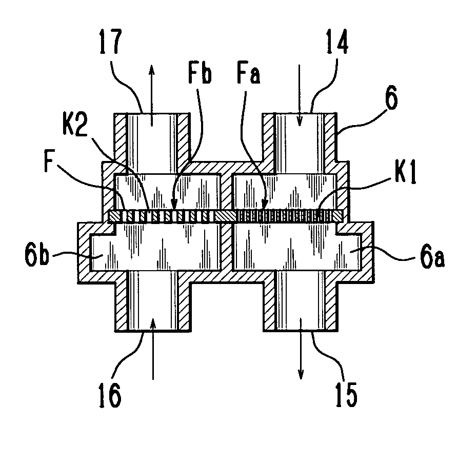
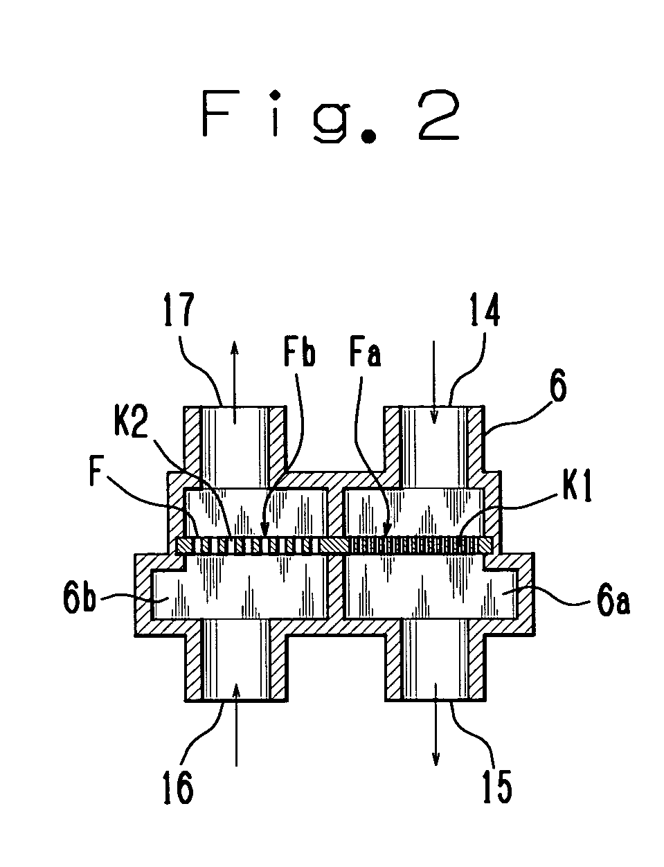
[0043] Next, the present invention will be described with reference to FIGS. 5 and 6. FIG. 5 is a cross sectional view schematically showing the ink channel in the ink jet apparatus. FIG. 6 is a longitudinal sectional view schematically showing the structure of the filter unit.

[0044] As the basic construction of the present embodiment is approximately the same as that of the first embodiment, only the difference from the first embodiment will be described. Note that the same elements have the same reference numerals and explanations thereof will be omitted.

[0045] A filter unit 30 has an ink distribution chamber 30a a part of which is the filter F, an ink distribution chamber 30b a part of which is the inflow filter Fa and which opposes the ink distribution chamber 30a via the inflow filter Fa, and an ink distribution chamber 30c a part of which is the outflow filter Fb and which opposes the ink distribution chamber 30a via the outflow filter Fb. Note that the ink distribution chamb...

first embodiment

[0050] As the ink flows through the inside of the ink jet head 2 in this manner, bubbles existing in the ink jet head 2 are moved with the ink to the outside. Thus the bubbles existing in the ink jet head 2 can be removed and the occurrence of ink discharge failure can be reliably suppressed with a simple construction. Further, as the ink is circulated, the consumption of ink can be suppressed and the cost can be reduced. Note that the present embodiment has the same advantages as those of the

[0051] Further, in the present embodiment, the filter unit 30 is provided which include therein the ink distribution chambers 30a and 30b which function as an ink inflow channel and the ink distribution chamber 30c connected to the ink distribution chamber 30a to function as an ink outflow channel. The inflow filter Fa is provided in the ink distribution chambers 30a and 30b which function as an ink inflow channel and the outflow filter Fb is provided in the ink distribution chamber 30c which f...

third embodiment

[0052] Next, the present invention will be described with reference to FIG. 7. FIG. 7 is a longitudinal sectional view schematically showing the structure of the filter unit.

[0053] As the basic construction of the present embodiment is approximately the same as that of the second embodiment, only the difference from the second embodiment will be described. Note that the same elements have the same reference numerals and explanations thereof will be omitted.

[0054] A filter unit 40 has a bubble chamber 41 in which bubbles passed through the outflow filter Fb are stored. The bubble chamber 41 is provided in an upper part of the filter unit 40 in a position above the outflow filter Fb. The filter unit 40 may be provided with a bubble removal mechanism (not shown) to discharge the bubbles, i.e., air gas, stored in the bubble chamber 41 to the outside. The bubble removal mechanism may be constituted of e.g. a pipe connecting the filter unit 40 and its outside to each other, a switching v...


PUM


Abstract

An ink jet apparatus where a filter is provided in an ink inflow channel connecting an ink tank with the inside of an ink jet head to discharge ink from nozzles, and in an ink outflow channel connecting the inside of the ink jet head with the ink inflow channel. The ink passes through the inside of the ink jet head, and bubbles existing inside the ink jet head move with the ink to the outside. Further, as foreign materials are repeatedly removed from the ink, bubbles in the ink jet head can be removed with a simple construction and the occurrence of ink discharge failure can be reliably suppressed.

Description

CROSS REFERENCE OF THE RELATED APPLICATION [0001] This application is based upon and claims the benefit of priority from the prior Japanese Application No. 2003-388057, filed on Nov. 18, 2003, the entire contents of which are incorporated herein by reference. BACKGROUND OF THE INVENTION [0002] 1. Field of the Invention [0003] The present invention relates to an ink jet apparatus which discharges ink as ink droplets. [0004] 2. Discussion of the Background [0005] Conventionally, an ink jet apparatus such as an ink jet printer discharges ink in an ink jet head from nozzles as ink droplets, onto a printing medium, thereby performs image formation. [0006] In this ink jet apparatus, the ink is supplied from an ink tank or the like to the ink jet head via an ink channel. When the ink contains foreign materials, clogging occurs in the nozzles of the ink jet head, which causes ink discharge failure. Accordingly, a filter for removal of foreign materials is provided in the ink channel, whereb...

Claims


Application Information

Patent Timeline
Patent Type & Authority Applications(United States)
IPC IPC(8): B41J2/175B41J2/18
CPCB41J2/18B41J2/17563
Inventor HIDA, SHINICHIRO
Owner TOSHIBA TEC KK
Why Eureka
Try Eureka