Oiling systems and methods for changing lengths of variable compression ratio connecting rods

a technology of compression ratio and connecting rod, which is applied in the direction of closed-circuit pressure lubricating system, pressure lubrication, engine components, etc., can solve the problem of typical dominance of engine knocking in a motor vehicl

Inactive Publication Date: 2002-06-04
FORD GLOBAL TECH LLC
View PDF7 Cites 24 Cited by
  • Summary
  • Abstract
  • Description
  • Claims
  • Application Information

AI Technical Summary

Problems solved by technology

However, those conditions that give rise to engine knocking in a motor vehicle typically prevail only for limited times as the vehicle is being driven.

Method used


Image

  • Oiling systems and methods for changing lengths of variable compression ratio connecting rods
  • Oiling systems and methods for changing lengths of variable compression ratio connecting rods
  • Oiling systems and methods for changing lengths of variable compression ratio connecting rods

Examples


first embodiment

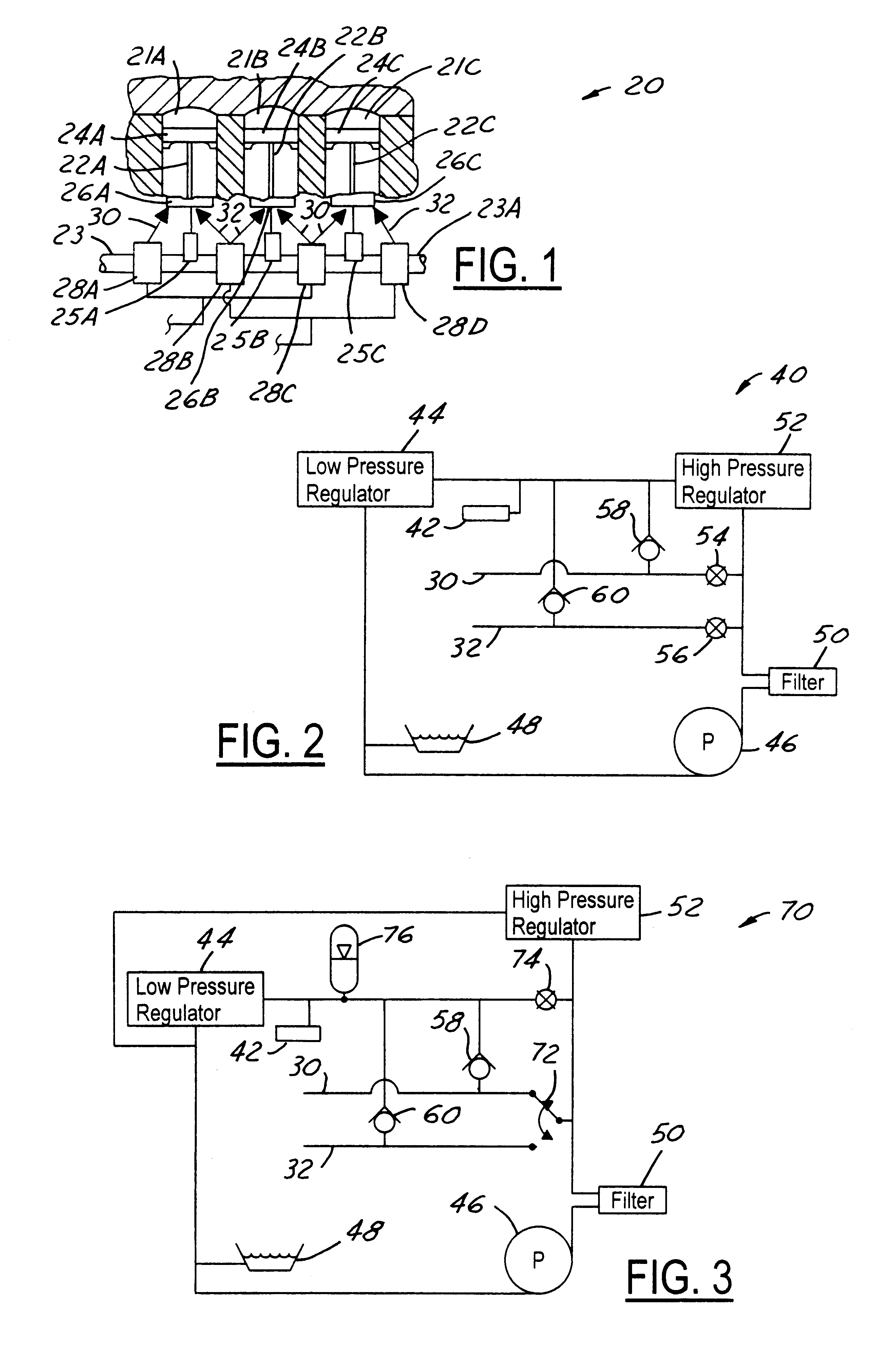
FIG. 2 shows hydraulic system 40 for effecting connecting rod length change integrated with an engine oiling system. The engine oiling system comprises a lubricating oil distribution system 42 comprising various galleries and passageways through which oil is delivered at nominal lubrication pressure for lubricating various moving surfaces within engine 20, including those surfaces mentioned earlier. In system 40, nominal lubrication pressure is established by a hydraulic device 44, an example of which is a low pressure regulator, or relief valve.

A pump 46, which may be driven by engine 20, draws oil from a sump 48, such as an engine oil pan, and supplies oil under pressure through a filter 50. The pressure of that supplied oil is established by a hydraulic device 52, an example of which is a high pressure regulator. Device 52 also provides a pressure drop for the supplied oil that allows device 44 to establish the nominal lubrication pressure. Excess oil returns from device 44 to su...

second embodiment

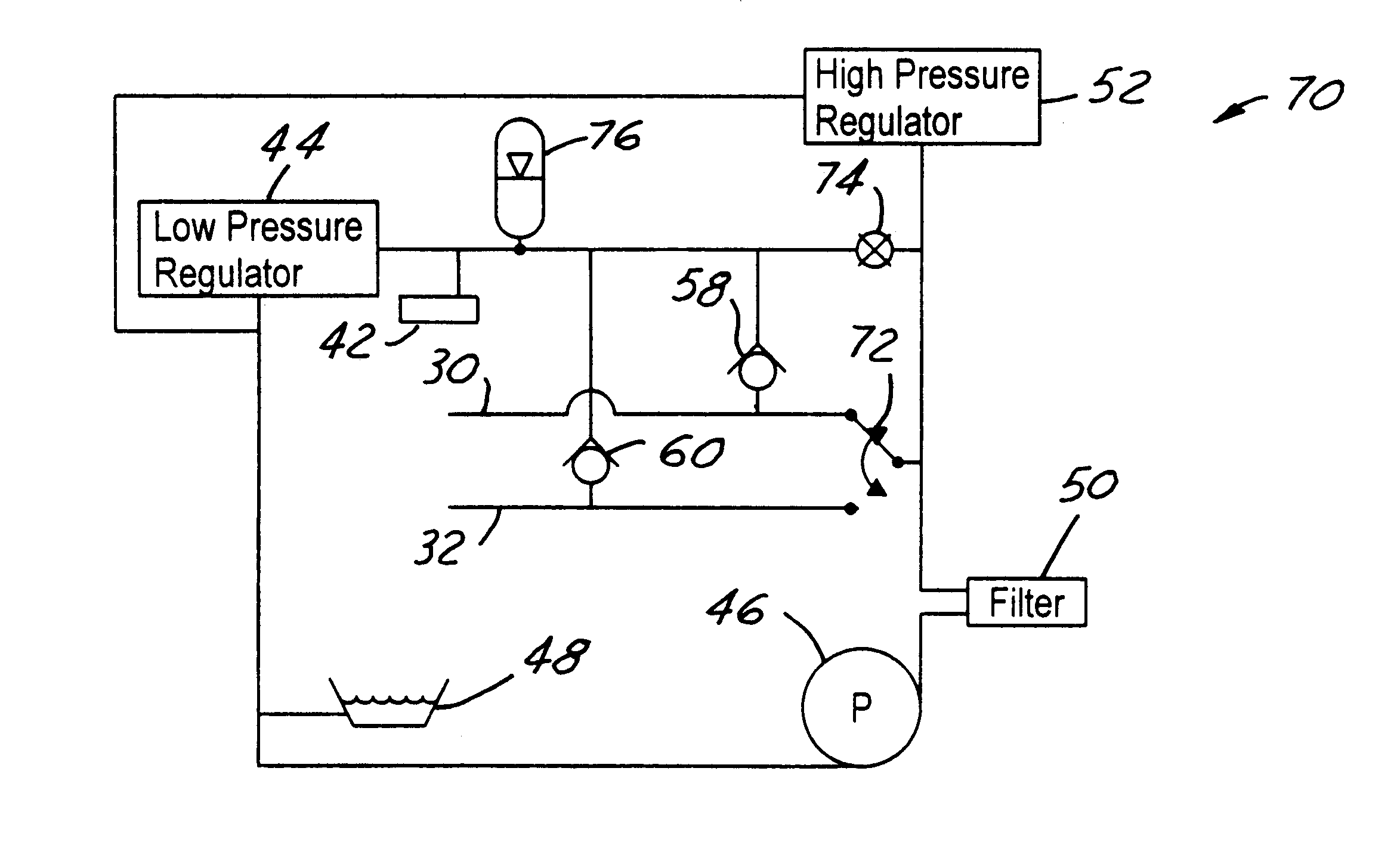
FIG. 3 shows hydraulic system 70 for effecting connecting rod length change in association with an engine oiling system. The oiling system comprises a lubricating oil distribution system 42 like that described in connection with FIG. 2. Like system 40, system 70 comprises a hydraulic device 44 (i.e. a low pressure regulator), a pump 46, a sump 48, a filter 50, a hydraulic device 52 (i.e. a high pressure regulator), and two check valves 58, 60. Additionally, system 70 comprises a selector valve 72, a normally open solenoid valve 74, and a low pressure hydraulic accumulator 76.

When connecting rod lengths are not being changed, valve 74 is not energized and therefore passes pumped oil flow. A portion of the flow is delivered to system 42 for lubrication, and a portion charges accumulator 76, at nominal lubrication pressure as established by low pressure regulator 44. Selector valve 72 communicates whichever one of passages 30, 32 it is selecting directly to the outlet of pump 46 via fi...

third embodiment

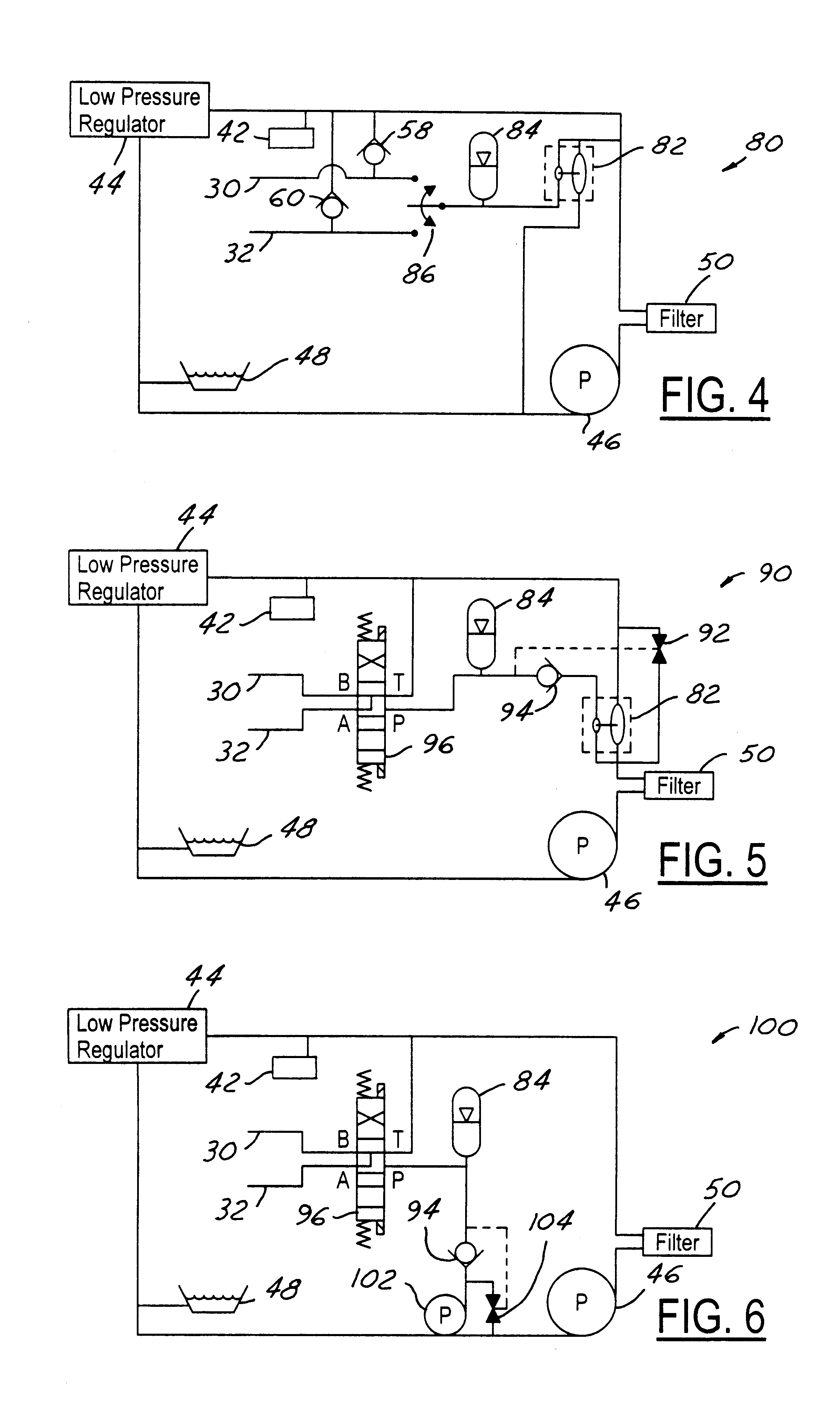
FIG. 4 shows hydraulic system 80 for effecting connecting rod length change in association with an engine oiling system. The oiling system comprises a lubricating oil distribution system 42 as previously described. System 80 comprises a hydraulic device 44, an example of which is a low pressure regulator, a pump 46, a sump 48, a filter 50, and check valves 58, 60. System 80 also comprises a hydraulic amplifier 82, a high pressure hydraulic accumulator 84, and a three-position selector valve 86.

Pump 46 supplies oil at nominal lubrication pressure established by low pressure regulator 44 for use by system 42, with some of the supplied oil passing through check valves 58 and 60 to passages 30 and 32 when no length change is being performed. Some of the pumped oil is used to operate hydraulic amplifier 82. When no length change is being performed, valve 86 is in a state that blocks both passages 30 and 32 from accumulator 84, enabling amplifier 82 to charge accumulator 84 with oil at a ...


PUM


Abstract

An engine 20 has an oiling system including a pump (46) that delivers oil under nominal engine lubrication pressure to lubricate moving surfaces of the engine mechanism (42). The system also has first and second control passages (30, 32) to effect engine compression ratio change by operating connecting rod length change mechanisms (26A, 26B, 26C). Selectively operated hydraulic control devices cause pressure in the first passage to be greater than pressure in the second passage to effect an increase in engine compression ratio and pressure in the second passage to be greater than pressure in the first passage to effect a decrease in engine compression ratio. Multiple embodiments of the invention are disclosed.

Description

1. Field of the InventionThis invention relates generally to reciprocating piston type internal combustion (I.C.) engines for motor vehicles. More specifically it relates to I.C. engines having variable compression ratio connecting rods, especially to systems, mechanisms, and strategies that use hydraulic fluid for accomplishing connecting rod length change while an engine is running.2. Background InformationThe compression ratio built into the design of an internal combustion engine that has a non-variable compression ratio must be selected to avoid objectionable engine knock that would otherwise occur during certain conditions of engine operation if the compression ratio were higher. However, those conditions that give rise to engine knocking in a motor vehicle typically prevail only for limited times as the vehicle is being driven. At other times, such as when it is lightly loaded, the engine could operate with better efficiency, and still without knocking, if the compression rat...

Claims


Application Information

Patent Timeline
Patent Type & Authority Patents(United States)
IPC IPC(8): F01M1/02F02B75/04F02B75/00F01M1/16F01M1/12F01M1/00
CPCF01M1/02F02B75/045F01M2001/123F01M1/16
Inventor STYRON, JOSHUA PUTMANIMAI, YASH ANDREWSCHWARTZ, GEORGE BYRONMORRISON, KEVIN MICHAEL
Owner FORD GLOBAL TECH LLC
Why Eureka
Try Eureka