Video transmission device and its method

a video transmission and video technology, applied in the field of video transmission devices, can solve the problems of inability to synchronize programs with each other, complex reception processing, and inability to immediately shift to another video data

Inactive Publication Date: 2002-06-11
SONY CORP
View PDF5 Cites 72 Cited by
  • Summary
  • Abstract
  • Description
  • Claims
  • Application Information

AI Technical Summary

Problems solved by technology

Therefore, the reception processing becomes complicated, and there is a possibility that it cannot be shifted to another video data immediately.
Moreover, in the case where the plurality of data are treated as separate programs, programs cannot be synchronized with each other.
Thus, there is a possibility that video data does not continue when the video data is shifted.

Method used


Image

  • Video transmission device and its method
  • Video transmission device and its method
  • Video transmission device and its method

Examples


Embodiment Construction

Preferred embodiments of this invention will be described with reference to the accompanying drawings:

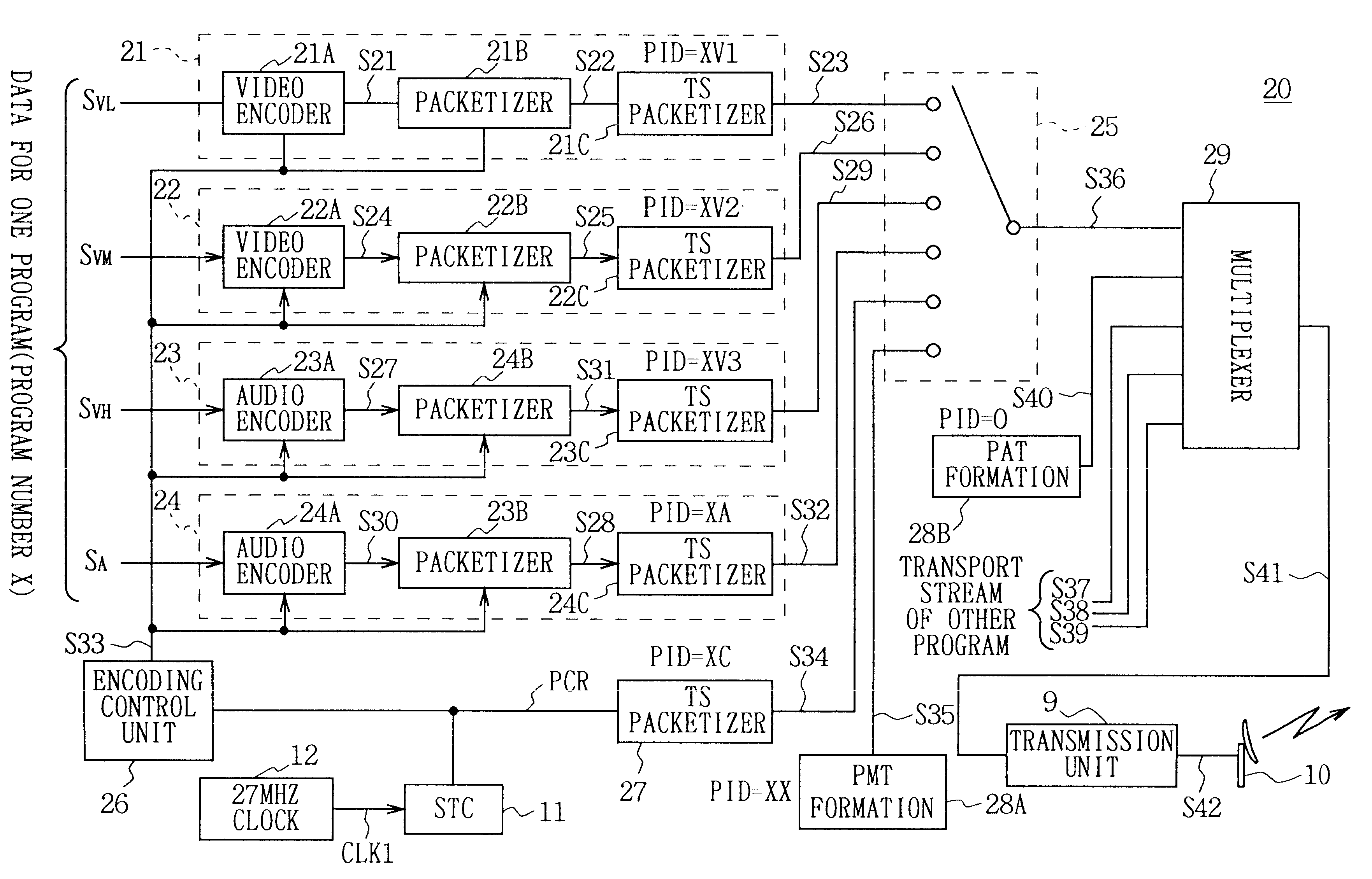
In FIG. 12, 20 generally shows a transmission device of a digital broadcasting system according to the present invention, which is to transmit a plurality of associated video data S.sub.VL, S.sub.VM and S.sub.VH as one program. More specifically, in the transmission device 20, low angle video data S.sub.VL obtained by photographing a concert by a prescribed musician from the lower part (hereinafter, referred to as first video data) is entered into a first video encoding unit 21, and middle angle video data S.sub.VM obtained by photographing the concert from the front (hereinafter, referred to as second video data) is entered into a second video encoding unit 22, and high angle video data S.sub.VH obtained by photographing the concert from the upper part (hereinafter, referred to as third video data) is entered into a third video encoding unit 23, and audio data S.sub.A accompanying ...


PUM


Abstract

In a video transmission device, a plurality of video data associated with one program can be transmitted without a complicated processing at the time of reception. In the case of transmitting a plurality of associated video data, first program information to control the plurality of associated video data as one program is formed and transmitted, so that the plurality of video data associated with one program can be transmitted without a complicated processing.

Description

1. Field of the InventionThe present invention relates to a video transmission device and its method and more particularly, is suitably applied to a digital broadcasting system.2. Description of the Related ArtA digital broadcasting system for multiplexing coded video and audio data to transmitting them through a satellite circuit has been proposed and become practical use. In this digital system, video data and also audio data are encoded, and by packetizing and multiplexing the coded video and audio data per fixed data unit, transport data (hereinafter, referred to as a transport stream) is formed and transmitted through such as a satellite wireless circuit.Here, the digital broadcasting system will be described with reference to FIG. 1. As shown in FIG. 1, a digital broadcasting system 1 is roughly comprised of a transmission device 2 to be set in a broadcasting station, a receiving device 3 and a television receiver 4 to be installed in each house. Transport stream data to be tr...

Claims


Application Information

Patent Timeline
Patent Type & Authority Patents(United States)
IPC IPC(8): H04N7/58H04N7/62H04N7/52H04N5/38H04J3/00H04N7/08H04N7/081H04N21/236H04N21/2362H04N21/242H04N21/43H04N21/434
CPCH04N21/23608H04N21/2362H04N21/242H04N21/4345H04N21/4307H04N21/4344H04N21/4305H04N21/43072
Inventor OBIKANE, NOBUHISA
Owner SONY CORP
Why Eureka
Try Eureka