Phase lock evoked response audiometer

Inactive Publication Date: 2002-06-18
UNIVERSITY OF MELBOURNE
View PDF4 Cites 14 Cited by
  • Summary
  • Abstract
  • Description
  • Claims
  • Application Information

AI Technical Summary

Benefits of technology

It is therefore an object of the present invention to provide an improved evoked response audiometer incorporating an i

Problems solved by technology

These evoked potentials can be difficult to detect, particularly for

Method used

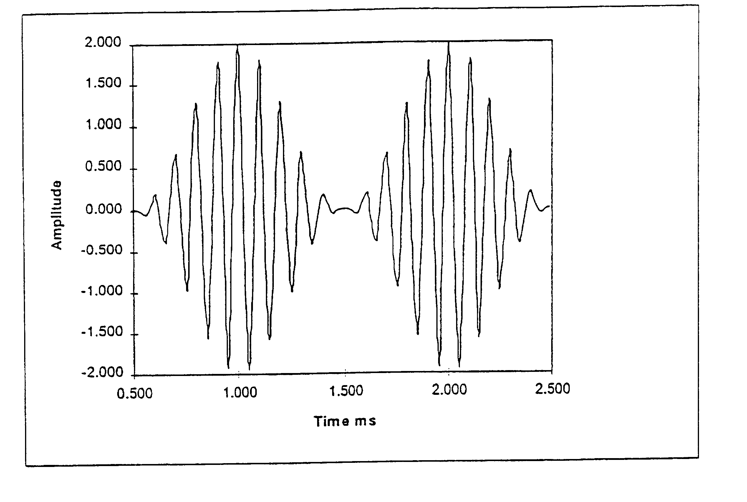
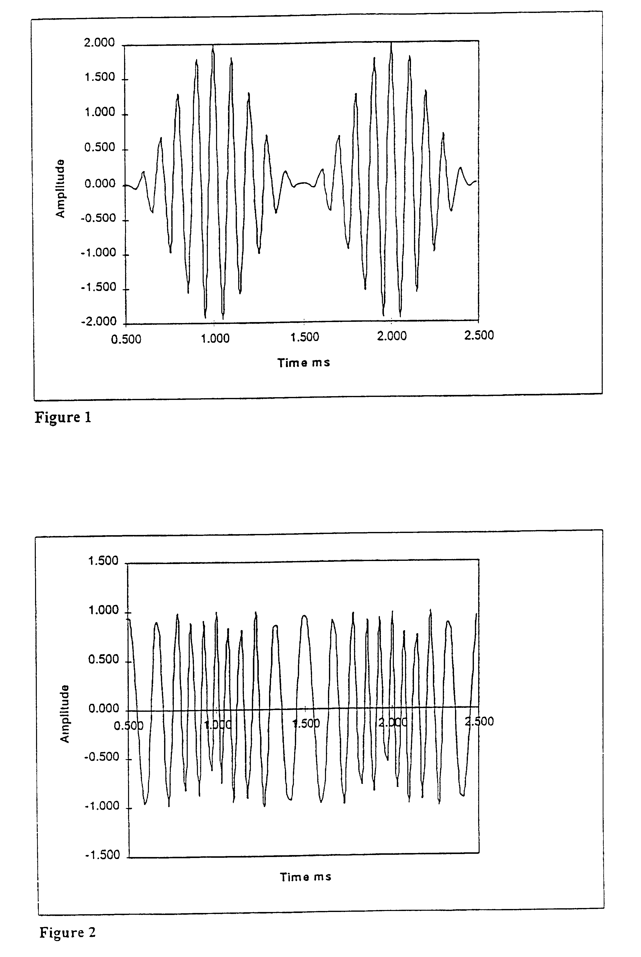
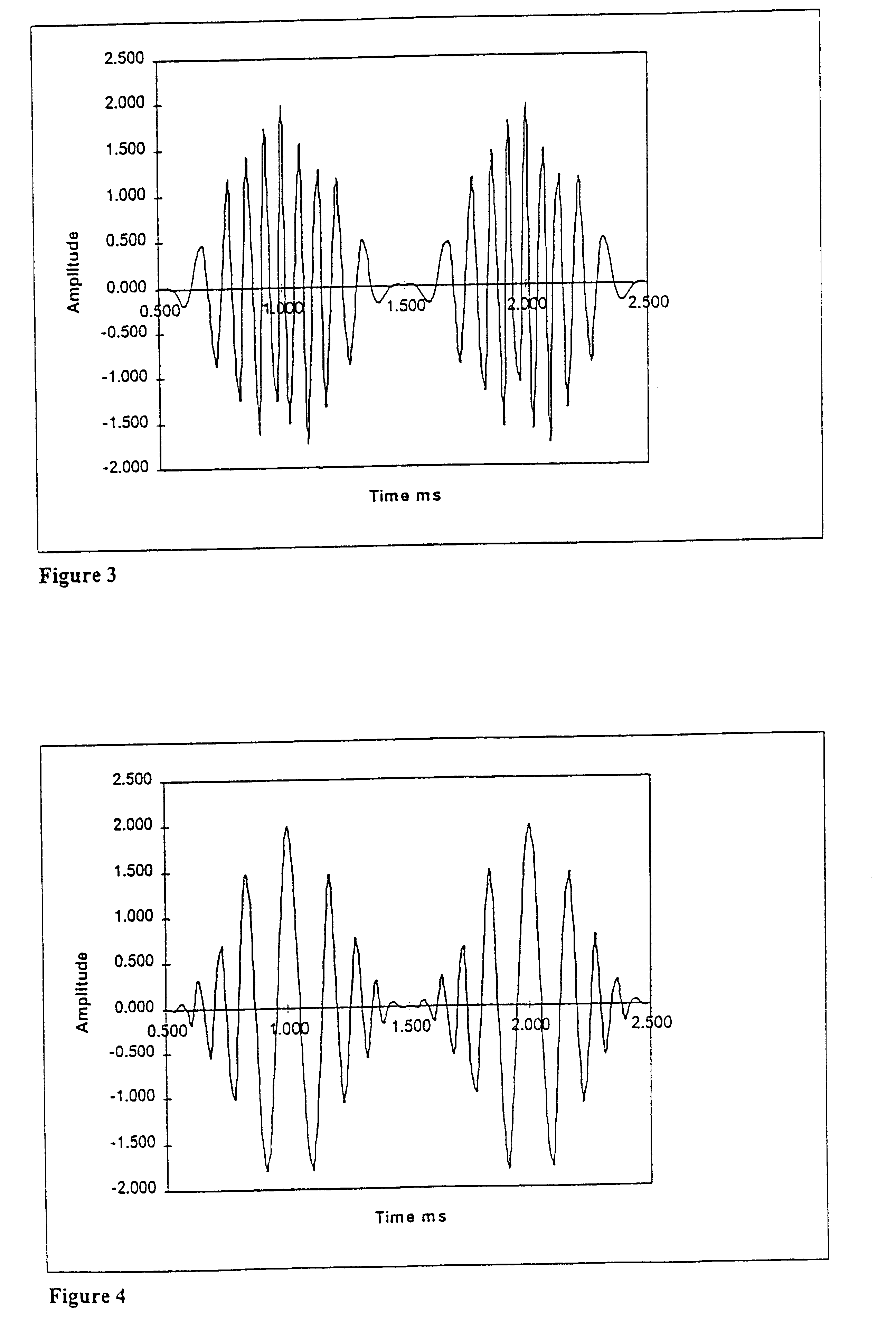

Image

  • Phase lock evoked response audiometer
  • Phase lock evoked response audiometer
  • Phase lock evoked response audiometer

Examples


Embodiment Construction

The evoked response audiometer embodying the invention uses digital signal processing (DSP) techniques for the generation of an auditory signal or stimulus and the detection of the response to the stimulus in the EEG activity representing the evoked potentials produced by the auditory signal. Consequently the processes used are implemented in software contained within the digital signal processor circuit used. This software is under direction of another software program which resides on a personal computer (PC) using Windows95.TM. or a similar computer and / or operating system.

Conventional signal processing algorithms used in the DSP software, when used in conjunction with each other, produce the required results. Frequency modulation and phase modulation are considered synonymous, as the modulation used is a single sinusoidal tone. Electronic hardware of the type described in our earlier U.S. Pat. Nos. 4,462,411 and 5,023,783, the contents of which are incorporated into the present ...


PUM


Abstract

An evoked response audiometer method and apparatus in which a patient receives an auditory stimulus signal comprising a carrier frequency which is periodically amplitude modulated and frequency modulated whereby the stimulus is at least substantially frequency specific, the brain potential signals of the patient evoked by the auditory signal being sampled to determine whether phase locking to the modulated auditory signal has occurred, the auditory signal being selectively controlled to advance or delay one modulation with respect to the other modulation to cause enhancement of the evoked response to the auditory stimulus.

Description

This invention relates to an improved evoked response audiometer for use in the diagnosis of deafness.The diagnosis of deafness at an early stage in paediatrics is important to enable the early fitting of hearing aids and / or cochlear implants in order to assist language development in a hearing-impaired child. It is also important to be able to diagnose deafness in adults who are unable, due to mental illness or disability, or unwilling, for various reasons, to participate in conventional behavioural deafness testing.In our U.S. Pat. Nos 4,462,411 (Rickards) and 5,023,783 (Cohen and Rickards), we have described evoked response audiometers which use a continuous auditory tone that is frequency or amplitude modulated, the auditory tone being presented for a sufficiently extended period of time to enable phase-locked steady-state potentials to be evoked in the brain of the person being tested. An electro-encephalograph (EEG) signal from the scalp of the person is manipulated such that ...

Claims


Application Information

Patent Timeline
IPC IPC(8): A61B5/12
CPCA61B5/121A61B5/04845A61B5/38
Inventor COHEN, LAWRENCE THOMASPARKER, JOHN CHARLESRICKARDS, FIELD WINSTON
Owner UNIVERSITY OF MELBOURNE
Why Eureka
Try Eureka