Eureka AIR delivers breakthrough ideas for toughest innovation challenges, trusted by R&D personnel around the world.

Bending die and bending machine using the same

Inactive Publication Date: 2002-07-02
LAPIS SEMICON CO LTD
View PDF1 Cites 4 Cited by
  • Summary
  • Abstract
  • Description
  • Claims
  • Application Information

AI Technical Summary

Benefits of technology

Accordingly, an object of the present invention is to provide a bending die in which friction contact with a lead is remarkably reduced.
Another object of the present invention is to provide a bending machine in which friction contact between a bending die and a lead is remarkably reduced.

Problems solved by technology

Since lead wires are extremely thin, they are weak or fragile and it is therefore necessary to use extreme care in bending them.
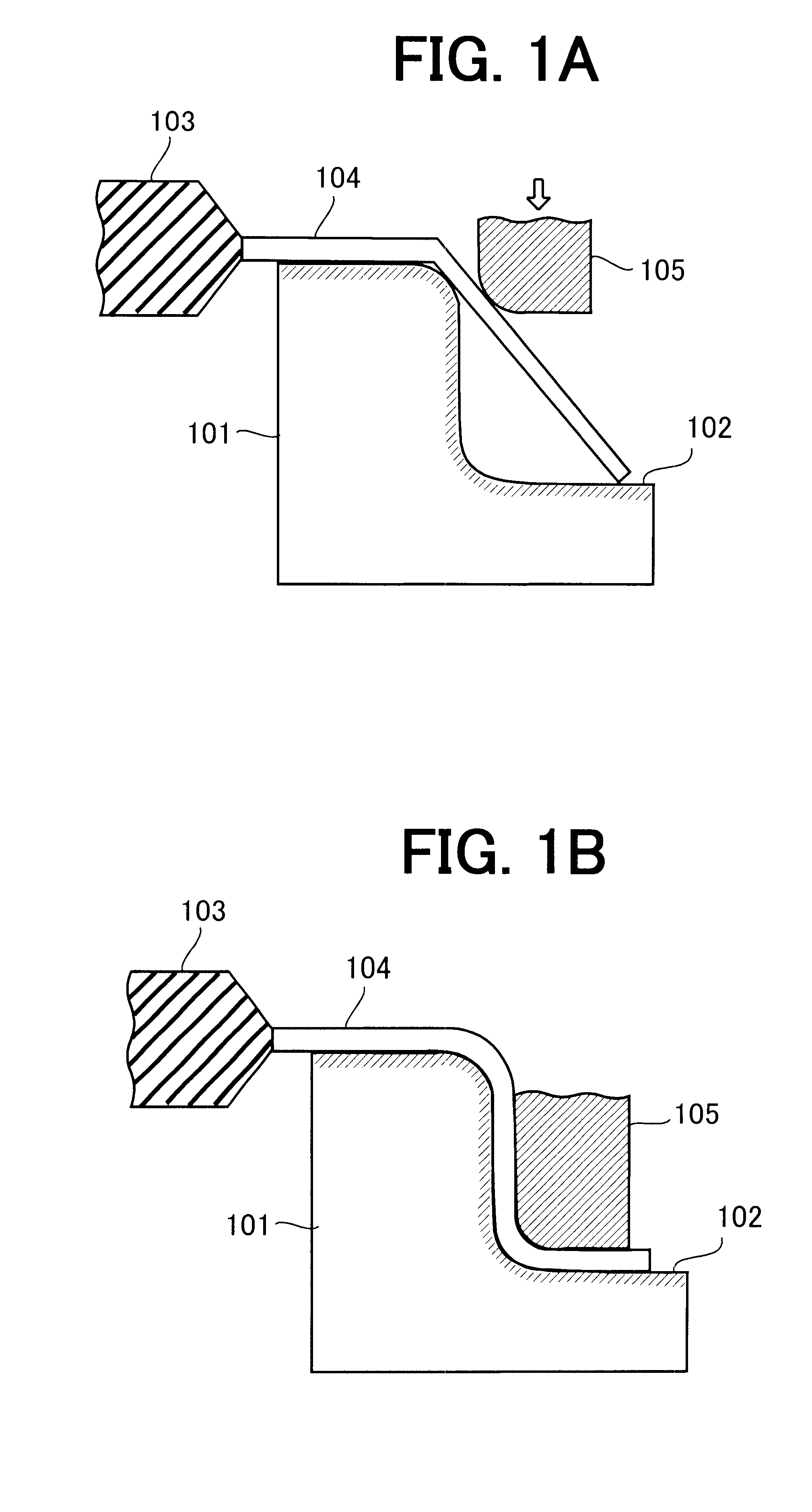
According to the above described conventional bending machine, even if the hard coating is made on the surface of the bending die, the ends of leads are scratched due to the frictional contact with the surface while the bending process is carried out.

Method used


Image

  • Bending die and bending machine using the same
  • Bending die and bending machine using the same
  • Bending die and bending machine using the same

Examples


Embodiment Construction

In the following detailed description of the preferred embodiments, reference is made to the accompanying drawings which forma part hereof, and in which is shown by way of illustration specific preferred embodiments in which the inventions may be practiced. These embodiments are described in sufficient detail to enable those skilled in the art to practice the invention, and it is to be understood that other embodiments may be utilized and that logical, mechanical and electrical changes may be made without departing from the spirit and scope of the present inventions. The following detailed description is, therefore, not to be taken in a limiting sense, and scope of the present inventions is defined only by the appended claims.

For better understanding of the present invention, a conventional technology is first described.

FIGS. 1A and 1B are side views showing steps of bending process using a conventional bending machine, which bends a lead 104 of a resin-molded IC package 103. The be...


PUM

PropertyMeasurementUnit
Currentaaaaaaaaaa
Currentaaaaaaaaaa
Levelaaaaaaaaaa

Abstract

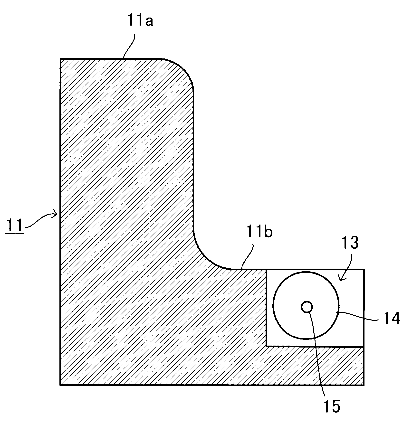
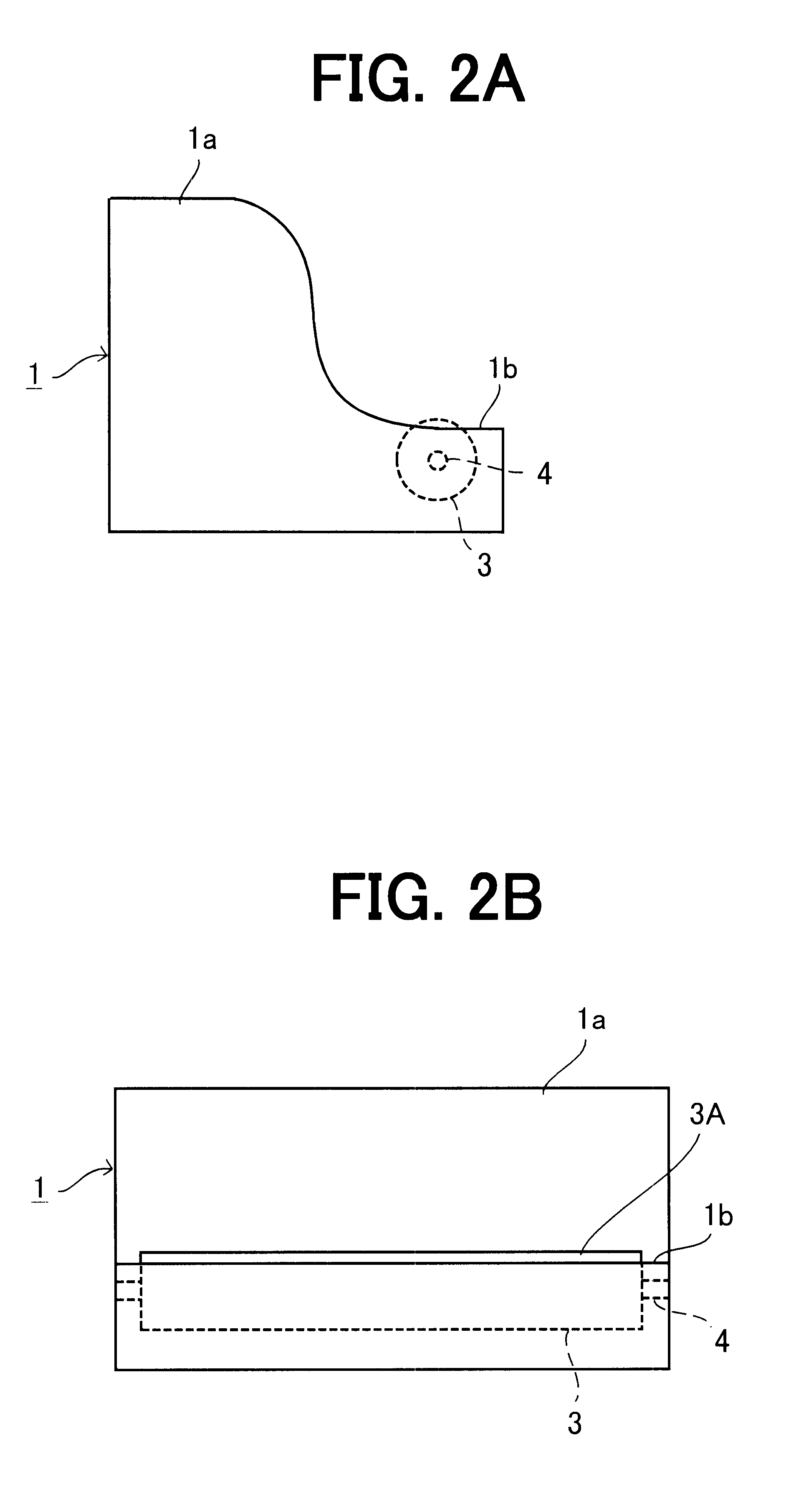
A bending die includes a base member (1, 11) and a roller (3, 14). The base member (1, 11) is provided with a first portion (1a, 11a), the root of a lead (5, 16) is in contact with, and a second portion (1b, 11b), the end (5A, 16A) of the lead (5, 16) is in contact with. The roller (3, 14) is arranged around the second portion (1b, 11b) of the base member (1, 11) to make rolling contact with the lead (5, 16) in bending operation.

Description

This application claims the priority of Application No. 2000-29917, filed Feb. 8, 2000 in Japan, the subject matter of which is incorporated herein by reference.The present invention relates to a bending machine for bending leads of an electric part, such as molded IC package. More particularly, the present invention relates to a bending die used for Z-bending an end portion of leads of a molded IC package, molded LSI package, etc.The mainstream of LSI mounting methods has been shifting from the conventional method employing DIPs (Dual In-line Packages) to the so-called surface mounting method in which a leaded electric part or device package is electrically connected to a conductor provided on the surface of a printed wiring board without using through-holes for insertion of lead wires. This shift is made to cope with an increase in the number of gates or the like as a result of the improvements of LSI chips, i.e., the achievement of high integration density, the increase in the nu...

Claims


Application Information

Patent Timeline
IPC IPC(8): B21F1/00H05K13/00H01L23/50
CPCB21F1/00H05K13/0092H01L2924/181H01L2924/00012
Inventor NAKASAKO, KOJI
Owner LAPIS SEMICON CO LTD
Why Eureka
Eureka Blog
Learn More