Rotation angle sensor having single wire windings and method for winding a rotation angle sensor

a technology of rotation angle sensor and winding, which is applied in the direction of electrical/magnetically converting the output of the sensor, continuously variable inductance/transformer, instruments, etc., can solve the problems of difficult process, difficult alignment, and destruction of the predetermined shape of the coiled winding, and achieves the effect of simple connection structure of the lead wir

Inactive Publication Date: 2006-05-16
MINEBEA CO LTD
View PDF6 Cites 15 Cited by
  • Summary
  • Abstract
  • Description
  • Claims
  • Application Information

AI Technical Summary

Benefits of technology

[0013]An objective of the invention is, by taking the above-mentioned problems into account, to provide a rotation angle sensor having a simple connection structure for the lead wires.
[0018]In another aspect of the invention, edges of the walls that define the notch are coated with a resin to provide the edges with a low friction surface. The resin is one that provides low friction contact. Thus, the wire will not be damaged by contact with the edges of the walls that define the notch
[0019]Therefore, in one aspect of the invention, the rotation angle sensor includes a coil bobbin of a rotor transformer, which has a notch on the side wall, and a laminated magnetic rotor core. The coil bobbin and the laminated core are located in a parallel relationship on a rotation shaft. A single electric wire is continuously coiled on the coil bobbin to form a rotor transformer. The same wire is continuously coiled on the laminated core to form a magnetic rotor winding. The wire passes from the rotary transformer to the magnetic rotor through the notch. First and second ends of the winding of the electric wire are connected through the notch and fixed on the rotor transformer winding with resin. Therefore, the rotor transformer winding and magnetic rotor winding are formed by a continuous winding of a single electric wire. In addition, only one connection is needed at only one location, allowing the length of electric wire to be shortened at only one place. Consequently, the electric effect and magnetic effect on the winding at the connection can be reduced compared to the prior art.

Problems solved by technology

The alignment is difficult because the finished winding may be mistakenly deformed by being pressed manually or the temporary insulation tape may detach, and the predetermined shape of the coiled winding may be destroyed.
The process is difficult to carry out in a small space, and thus, long lead wires must be employed.
Unlike the winding portion, the long lead wires may generate an irregular magnetic field that has an effect on the basic magnetic field, which is based on the designated number of windings, and may create an uneven weight distribution, which may cause oscillations during the rotation.
Further, the long lead wires may cause a restriction such that the interval between the rotor transformer and magnetic rotor cannot be narrowed.

Method used


Image

  • Rotation angle sensor having single wire windings and method for winding a rotation angle sensor
  • Rotation angle sensor having single wire windings and method for winding a rotation angle sensor
  • Rotation angle sensor having single wire windings and method for winding a rotation angle sensor

Examples


Embodiment Construction

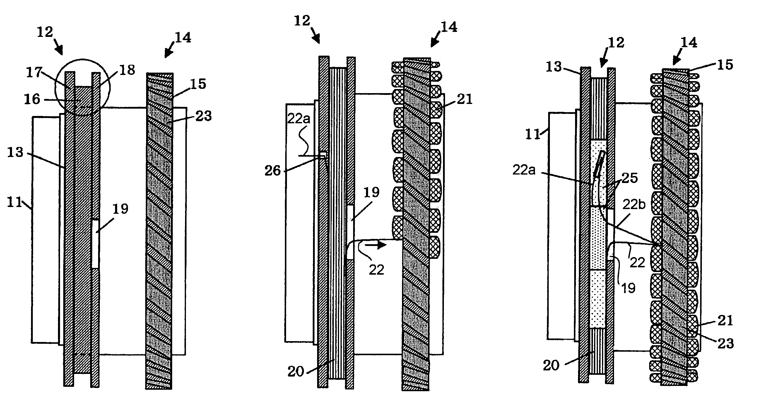
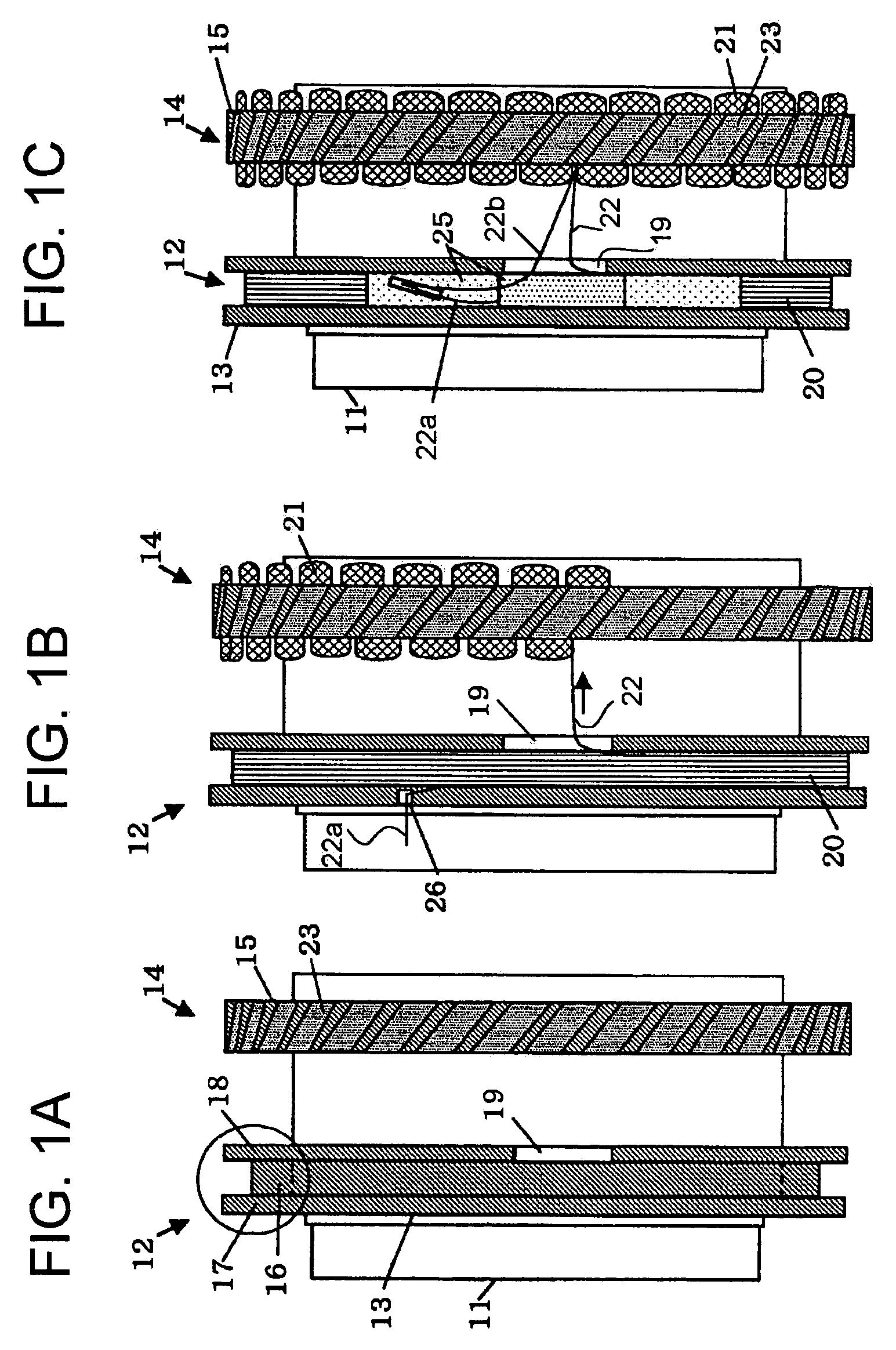
[0035]FIG. 1 shows an initial stage of the winding process for a magnetic rotor 14 and a rotor transformer 12 of a rotation angle sensor of the present invention. FIG. 1A shows a laminated core 15 of the magnetic rotor 14 and a coil bobbin 13 of the rotor transformer 12 prior to initiation of coiling. FIG. 1B shows the laminated core 15 of the magnetic rotor 14 and the coil bobbin 13 of the rotor transformer 12 during the coiling process, and FIG. 1C shows the laminated core 15 of the magnetic rotor 14 and the coil bobbin 13 of the rotor transformer 12 after the coiling is completed. The rotation angle sensor includes a stator (not shown) and the magnetic rotor 14 for excitation and detection. In addition, the rotation angle sensor includes a stator transformer (not shown) and the rotor transformer 12 for the electric supply.

[0036]First, as shown in FIG. 1A, the coil bobbin 13 of the rotor transformer 12 and the laminated core 15 of the magnetic rotor 14 are fitted to a hollow rotat...


PUM

PropertyMeasurementUnit
frictionaaaaaaaaaa
structureaaaaaaaaaa
magneticaaaaaaaaaa

Abstract

A rotation angle sensor and a method of winding a rotation angle sensor involve a single electrical wire that is wound from a rotor transformer to a magnetic rotor. The magnetic rotor is axially spaced on a shaft from the rotor transformer. A notch is formed in a wall of a bobbin of the rotor transformer to permit the wire to pass from the rotor transformer to the magnetic rotor. The ends of the single wire are electrically connected together at a junction, and the junction is fixed to the rotor transformer with resin.

Description

CROSS REFERENCE TO RELATED APPLICATION[0001]This application is based on and incorporates by reference Japanese Patent Application No. 2003-275952, which was filed on 17 Jul. 2003.BACKGROUND OF THE INVENTION[0002]The present invention relates to a rotation angle sensor that includes a brushless resolver having a transformer and a magnetic rotor and to a method for winding a rotation angle sensor, and in particular, to a rotation angle sensor in which a rotor transformer winding and a magnetic rotor winding are wound with a single wire.[0003]A brushless resolver has a transformer winding such that, in addition to the rotor and stator for excitation and detection, the resolver includes a transformer for a power supply. FIG. 5 shows an example.[0004]FIG. 5 is a cross-sectional view of the structure on the rotor of a conventional resolver. The structure of the stator is omitted. FIG. 5 shows the rotor structure including a rotor 102 having bobbin 103 integrally formed with the rotation ...

Claims


Application Information

Patent Timeline
Patent Type & Authority Patents(United States)
IPC IPC(8): G01L3/14G01D5/245G01D5/20H02K24/00
CPCG01D5/2006
Inventor KOYAMA, TOSHISADAMATSUURA, MUTSUMISANO, TAKASHI
Owner MINEBEA CO LTD
Why Eureka
Try Eureka