Servo control apparatus and method for compensating for axial vibration of an optical disk

a technology of axial vibration and servo control, which is applied in the direction of digital signal error detection/correction, instruments, recording signal processing, etc., can solve the problems of limited maximum rotation speed of optical disk, impossible normal data readout,

Inactive Publication Date: 2002-07-02
LG ELECTRONICS INC
View PDF4 Cites 21 Cited by
  • Summary
  • Abstract
  • Description
  • Claims
  • Application Information

AI Technical Summary

Problems solved by technology

In the instance where the axial vibration of the optical disk caused by imperfect disk manufacturing process, disk clamping error, or disk tilt exceeds a certain limit, tracking and focusing control may yield large errors and thus normal

Method used


Image

  • Servo control apparatus and method for compensating for axial vibration of an optical disk
  • Servo control apparatus and method for compensating for axial vibration of an optical disk
  • Servo control apparatus and method for compensating for axial vibration of an optical disk

Examples


Embodiment Construction

In order that the invention may be fully understood, preferred embodiments thereof will now be described with reference to the accompanying drawings.

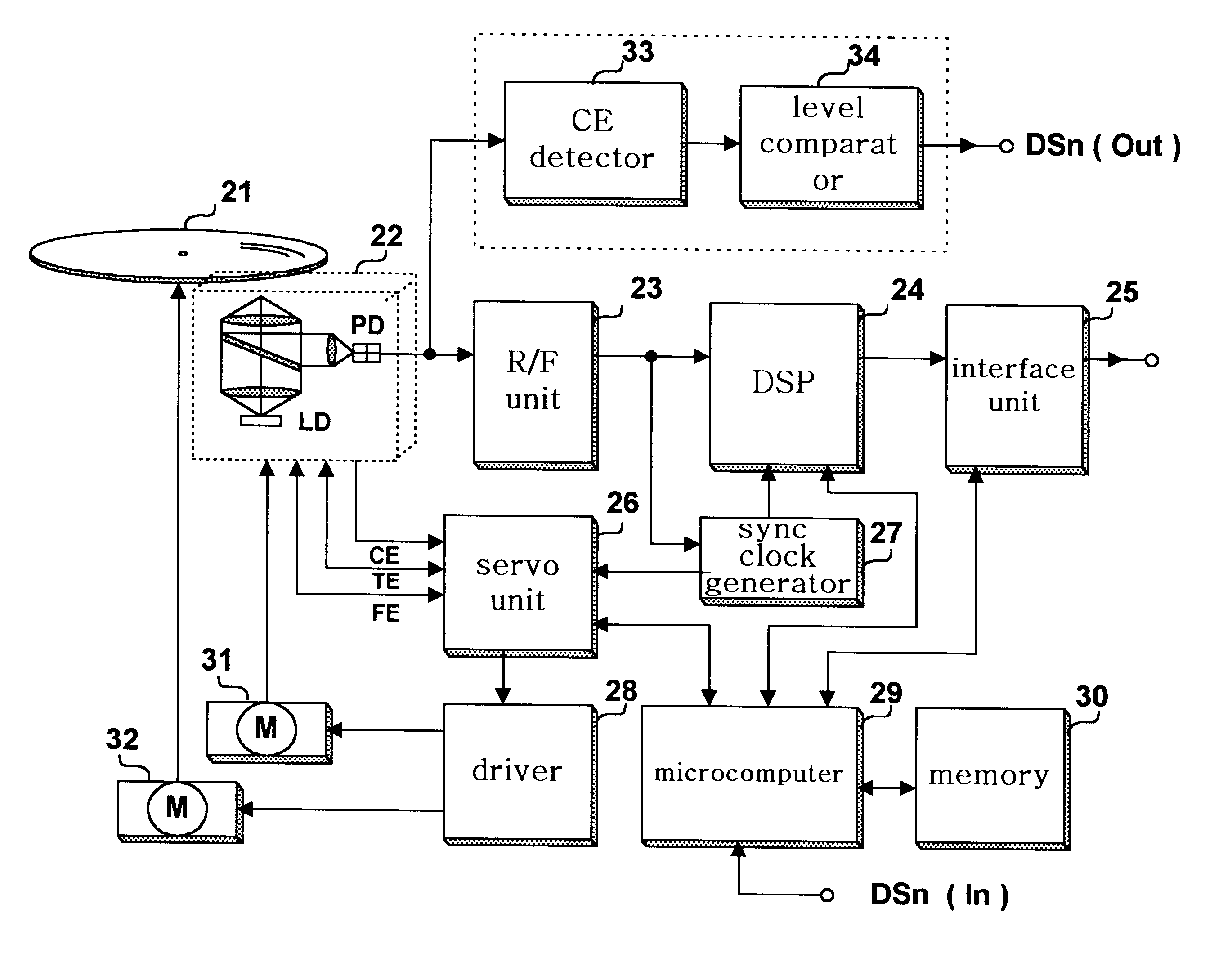
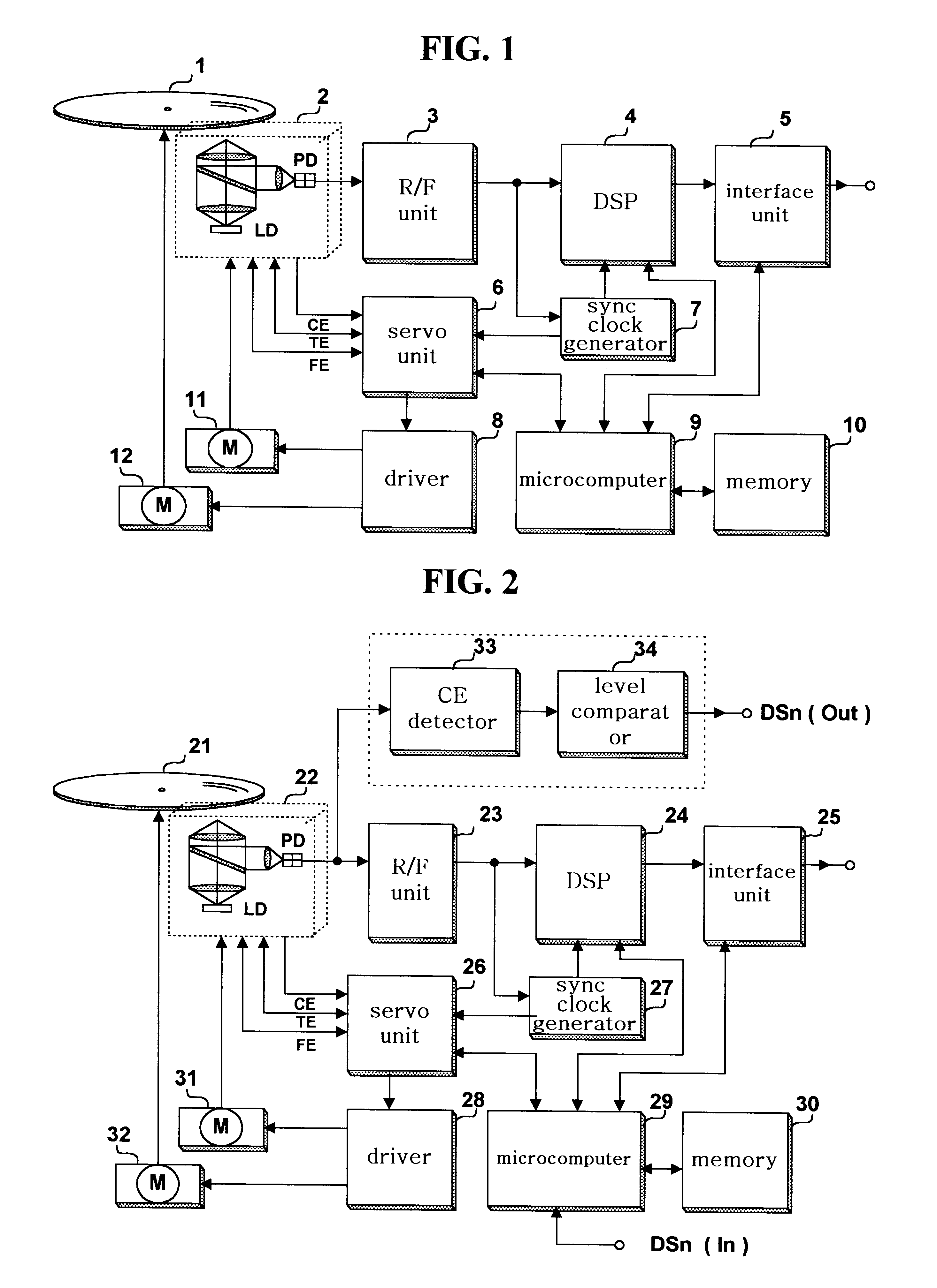
FIG. 2 depicts an optical disk reproducing apparatus in which the present invention may be advantageously practiced. The apparatus comprises an optical pickup 22 for reproducing recorded signals from an optical disk 21, an R / F unit 23 for equalizing and shaping the RF signals reproduced by the optical pickup 22, a sync clock generator 27 for creating a clock signal synchronized with the binary data outputted from the R / F unit 23, a digital signal processing unit 24 for processing the binary data stream received from the R / F unit 3 to retrieve digital data using the synchronization clock, an interface unit 25 for connecting the retrieved digital data to a PC, a sled motor 31 for moving the optical pickup 22, a spindle motor 32 for rotating the optical disk 21, a driver 28 for driving the sled motor 31 and the spindle motor 32, a servo un...


PUM


Abstract

A servo control apparatus and method that adjust the allowable maximum rotation speed of an optical disk based upon the amount of disk axial vibration. The servo control apparatus in accordance with the present invention includes a driver for rotating the optical disk, a detector for detecting the amount of axial vibration of the optical disk, and a controller for controlling the rotation speed of the optical disk based upon the detected amount of disk axial vibration. The servo control apparatus and method in accordance with the present invention prevents data read error due to disk axial vibration by adjusting the allowable maximum disk rotation speed in consideration for the amount of disk axial vibration caused by imperfect disk manufacturing process, disk clamping error, or disk tilt.

Description

1. Field of the InventionThe present invention relates to an apparatus and method for servo control of an optical disk drive, and more particularly, but not by way of limitation, to servo control apparatus and method that adjusts the rotation speed of an optical disk in consideration of the amount of axial vibration of the optical disk.2. Description of the Related ArtShown in FIG. 1 is a general optical disk reproducing apparatus, comprising an optical pickup 2 for reproducing recorded signals from an optical disk 1, an R / F unit 3 for equalizing and shaping the RF signals reproduced by the optical pickup 2, a sync clock generator 7 for creating a clock signal synchronized with the binary data outputted from the R / F unit 3, a digital signal processing unit 4 for processing the binary data stream received from the R / F unit 3 to retrieve digital data using the synchronization clock, an interface unit 5 for connecting the retrieved digital data to a PC, a sled motor 11 for moving the o...

Claims


Application Information

Patent Timeline
IPC IPC(8): G11B19/28G11B7/09G11B7/095G11B19/20
CPCG11B7/0945G11B19/28G11B7/0953G11B7/0956G11B19/20
Inventor KIM, JIN SEON
Owner LG ELECTRONICS INC
Why Eureka
Try Eureka