Dual loop vehicle air conditioning system

a dual-loop vehicle and air conditioning technology, which is applied in vehicle components, vehicle heating/cooling devices, refrigerating machines, etc., can solve the problems of insufficient generator power to keep the air conditioning system in operation, inability to provide as much electrical power, and no one has successfully devised a way to utilize a dual-loop system

Inactive Publication Date: 2002-07-09
FERDOWS HOUSHANG K
View PDF8 Cites 44 Cited by
  • Summary
  • Abstract
  • Description
  • Claims
  • Application Information

AI Technical Summary

Problems solved by technology

The problems in air conditioning systems for vehicles other than trains or railway cars are somewhat different in that, for example, in a bus air conditioning system the generator does not have the same capacity as the power source used on railway cars and is not capable of providing as much electrical power; also, under peak load conditions, there may be insufficient power from the generator to keep the air conditioning system in operation.
For this reason, in the past, no one has successfully devised a way of utilizing a dual loop system on a bus or other vehicle in which a generator is employed as the power source to continue to run the system under peak load conditions.

Method used


Image

  • Dual loop vehicle air conditioning system
  • Dual loop vehicle air conditioning system
  • Dual loop vehicle air conditioning system

Examples


Embodiment Construction

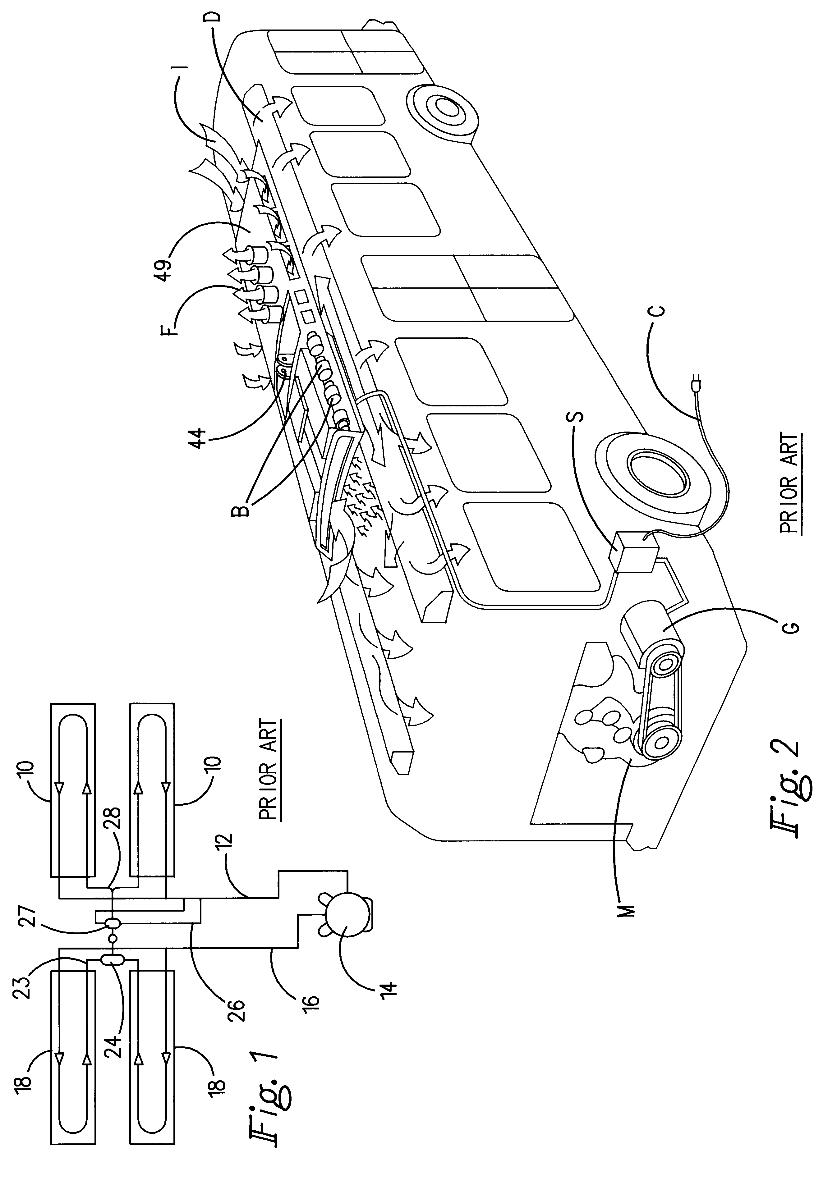
A prior art air conditioning system for busses is schematically shown in FIGS. 1 and 2 in which FREON.RTM. or other refrigerant in its gaseous state is drawn from evaporator coils 10 through a suction line 12 into compressor 14 which is driven off of a bus engine M. During compression, the cool FREON.RTM. gas undergoes both an increase in temperature and pressure and is then discharged by the compressor through line 16 into condenser coils 18. As the gas circulates internally through the coils 18, ambient air is drawn through the coil fins by a combination of centrally located condenser fans F and side air inlets I, as shown in FIG. 2. The FREON.RTM. gas is liquefied as the air is drawn across the condenser coils 18 and by the increased pressure of the gas created by the compressor 14. Any heat given up by the gas in its conversion into liquid form is expelled by the condenser fans F. The, liquid refrigerant from the condenser coils 18 is delivered into a receiver / dryer 24 via the r...


PUM


Abstract

A vehicle air conditioning system is specifically adaptable for mounting on the roof of a bus and is made up of condenser sections in which air is circulated across each of the condensor sections, a pair of evaporator sections with air circulated across the evaporator sections in the usual manner, and a pair of compressors are arranged in a double loop refrigerant system between the condenser and evaporator sections in such a way that each compressor delivers refrigerant to one of the condensor sections from which the refrigerant is then advanced to one or more evaporator coils in each of the evaporator sections.

Description

BACKGROUND AND FIELD OF INVENTIONThis invention relates to vehicle air conditioning systems; and more particularly relates to a novel and improved air conditioning system which employs a pair of compressors interconnected between condenser and evaporator sections in a unique and highly efficient manner.Railway car air conditioning units customarily employ a high voltage power source that is capable of providing enough electrical power to run a pair of roof-mounted compressors between a pair of condensers and pair of evaporators. In such systems, however, the compressors are independently connected between one of the condensers and evaporators so as to in effect define a pair of single loop systems. In that way, if one of the single loop systems becomes inoperable, the other one would continue to deliver conditioned air to the interior of the railway car from the one evaporator section still in use.The problems in air conditioning systems for vehicles other than trains or railway car...

Claims


Application Information

Patent Timeline
Patent Type & Authority Patents(United States)
IPC IPC(8): B60H1/00
CPCB60H1/00371B60H2001/00235Y10S62/16B60H1/00542
Inventor FERDOWS, HOUSHANG K.
Owner FERDOWS HOUSHANG K
Why Eureka
Try Eureka