Method and device for forming tubular work into shaped hollow product by using tubular hydroforming

a technology of tubular work and hydroforming, which is applied in the field of tubular hydroforming, can solve the problems of difficult to provide a hydroformed hollow product that gives users satisfaction, cracks tend to appear at the portion that has been subjected to wall thinning, and corner portions remote from the center of the work are particularly attacked

Inactive Publication Date: 2002-07-09
NISSAN MOTOR CO LTD
View PDF7 Cites 31 Cited by
  • Summary
  • Abstract
  • Description
  • Claims
  • Application Information

AI Technical Summary

Problems solved by technology

However, due to the nature of deformation of the material of the tubular work during the hydroforming process, it has been difficult to provide a hydroformed hollow product that gives users satisfaction.
In fact, in the pre-forming step, even when aluminum and/or high strength steel tube is used as the tubular work, a crack tends to appear at a portion that has been subjected to a wall thinning during the expansion of the work.
Furthermore, in the pre-forming step

Method used


Image

  • Method and device for forming tubular work into shaped hollow product by using tubular hydroforming
  • Method and device for forming tubular work into shaped hollow product by using tubular hydroforming
  • Method and device for forming tubular work into shaped hollow product by using tubular hydroforming

Examples


first embodiment

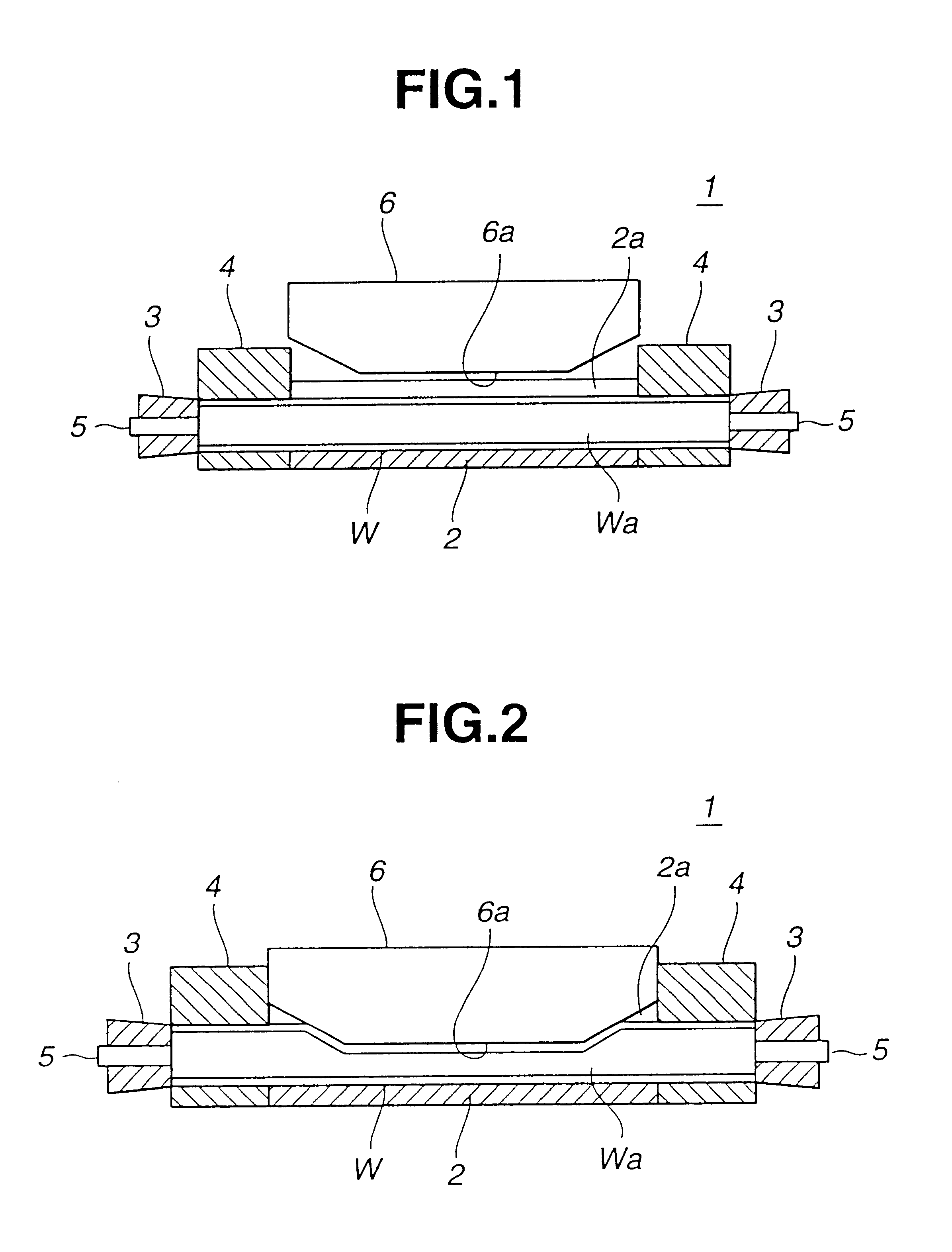
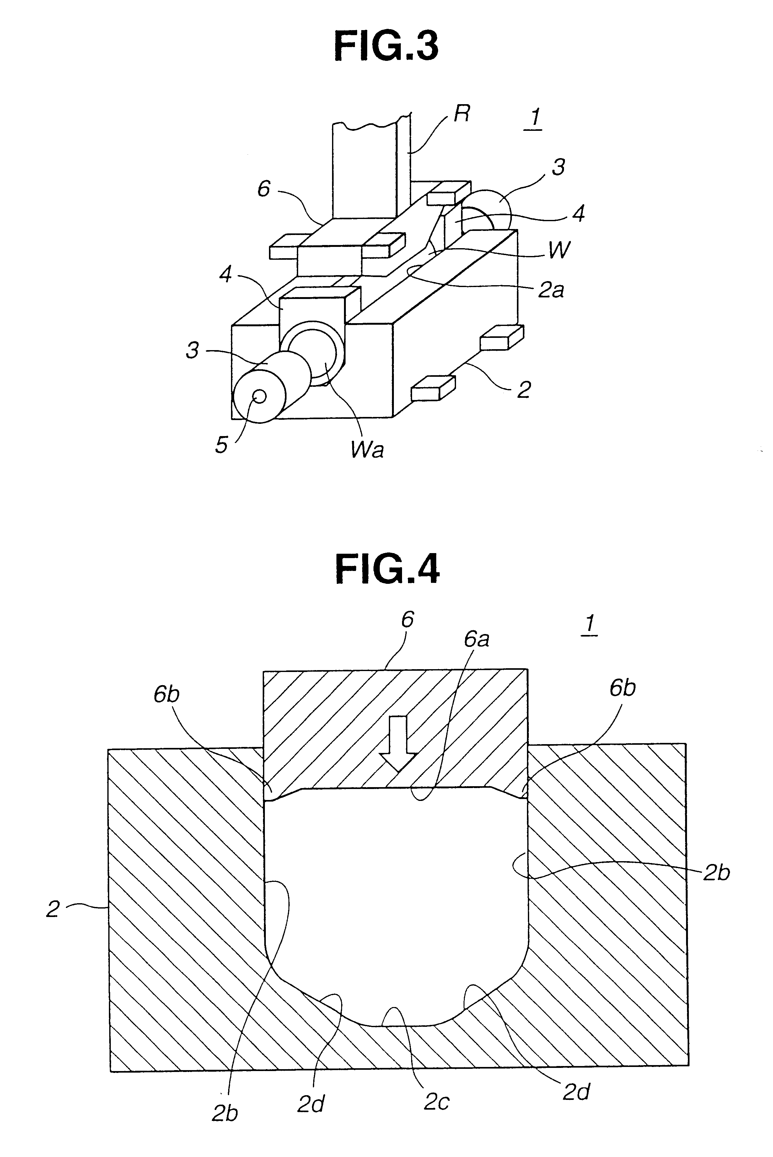
Referring to FIGS. 1 to 8, particularly FIGS. 1 to 4, there is shown a hydroforming device 1 with which a method of the present invention is practically carried out.

As will become apparent as the description proceeds, the explanation will be made with respect to a process for producing an automotive side roof rail S (see FIG. 37) as an example of the final component or a shaped hollow product.

As is seen from FIGS. 1 to 4, the hydroforming device 1 comprises generally a female die 2 which has a cavity 2a formed therein, two sealing tools 3 which seal both open ends of a tubular work W, two supporting members 4 which stably support both end portions of the tubular work W while having a major portion of the tubular work W put in the cavity 2a of the female die 2, two feeding tubes 5 which feed and draw a hydraulic fluid into and from an interior Wa of the tubular work W whose ends are sealed by the sealing tools 3 and a male die 6 which presses the tubular work W in the cavity 2a of th...

second embodiment

Referring to FIG. 9, there is schematically shown a female die 22 employed in a hydroforming device 21 with which a method of the present invention is carried out.

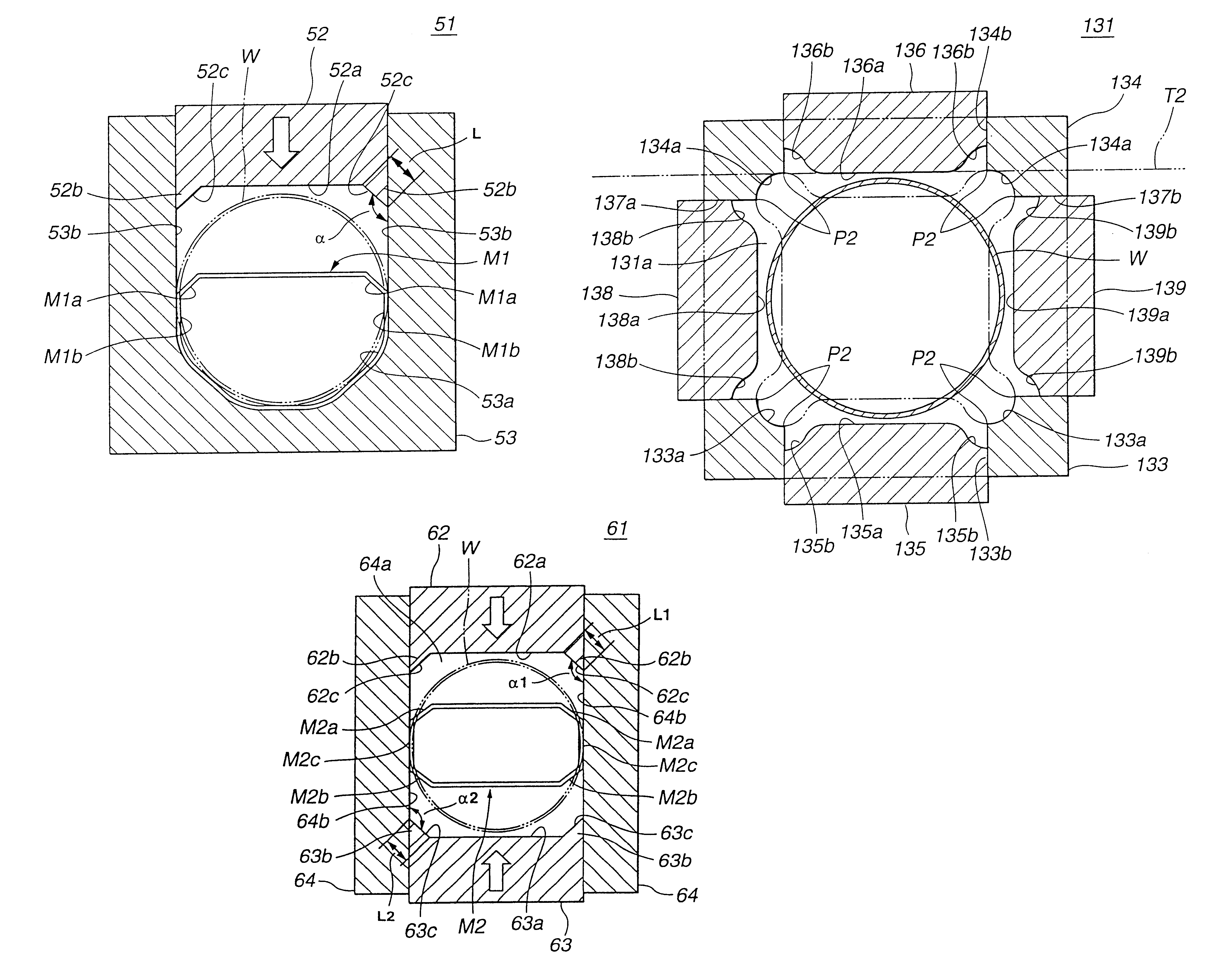
As is seen from the drawing, the female die 22 is formed with an axially extending stepped portion 22g between each vertical wall 22b and the adjacent slanted wall 22d. Preferably, the size of the stepped portion 22g is smaller than the thickness of the tubular work W and greater than one tenth (viz., 1 / 10) of the thickness of the work W. Denoted by numeral 22a is a cavity defined by the female die 22. Several tests have revealed that the presence of such stepped portions 22g lessens the possibility of producing undesired buckling of the tubular work W during the forming process. Furthermore, the tests have revealed that the presence of the stepped portions 22g assuredly reduces the stroke length of the male die.

third embodiment

Referring to FIGS. 10 and 11, particularly FIG. 10, there is shown but partially and in a sectional manner a female die 32 employed in a hydroforming device 31 with which a method of the present invention is carried out.

As is seen from FIG. 10, in this female die 32, there is formed, between each vertical wall 32b and the corresponding slanted wall 32d, with an extra slanted wall 32g that defines an angle ".theta." relative to the vertical wall 32b. Preferably, the angle ".theta." is within a range from 0 to 45.degree.. Denoted by numeral 32a is a cavity defined by the female die 32. Tests have revealed that due to presence of such extra slanted walls 32g, the friction inevitably produced between the wall of the female die 32 and the male die 6 can be reduced and the pressing load applied by the male die 6 is evenly transmitted to the entire construction of the work W.

For finding a desired value of the angle ".theta." in case wherein the hydroforming process reduces the circumferent...


PUM

PropertyMeasurementUnit
Fractionaaaaaaaaaa
Angleaaaaaaaaaa
Angleaaaaaaaaaa

Abstract

For forming a tubular work into a shaped hollow product by using hydroforming process, a method and a device are described. In the method, female and male dies are prepared. The female die has a longitudinally extending cavity which has a polygonal cross section when receiving the male die. The tubular work is placed into the cavity of the female die. The interior of the tubular work is then fed with a hydraulic fluid, and the pressure of the fluid is increased to a given level. The given level is smaller than a critical level that causes a bulging of the tubular work. The male die is then pressed against the tubular work to deform the same while keeping the hydraulic fluid at the given level, thereby forming a shaped hollow product that has a polygonal cross section that conforms to that of the cavity. The pressing work is continued until a circumferential length of the shaped hollow product becomes shorter than that of the tubular work.

Description

1. Field of the InventionThe present invention relates in general to tubular hydroforming and more particularly to method and device for forming a tubular work into a shaped hollow product by using hydroforming process. More specifically, the present invention relates to method and device for producing an automotive hollow part, such as front pillar, center pillar, roof rail or the like, by using tubular hydroforming process.2. Description of the Prior ArtTubular hydroforming process is a novel process that has recently gained much attention due to its cost-effective application particularly in the automotive industry. As is known, the tubular hydroforming is of a process that includes major steps wherein ends of a tubular work in a net shape die unit are sealed and a hydraulic fluid is pumped in the tubular work and pressurized to deform cross-sections of the work to conform to a cross section of the net shape die. Usually, before the major steps, a pre-forming is made wherein for ...

Claims


Application Information

Patent Timeline
IPC IPC(8): B21D22/12B21D22/00B21D22/10
CPCB21D22/105B21D22/125
Inventor SAKURAI, HIROSHINAKANISHI, EIZABUROUOOE, SHINJIHAYASAKA, MASANOBUKATAMURA, JUNJI
Owner NISSAN MOTOR CO LTD
Why Eureka
Try Eureka