
Substrate for use in wet capacitors

a technology of substrate and capacitor, which is applied in the direction of surface reaction electrolytic coating, metal-working apparatus, electrochemical machining apparatus, etc., can solve the problems of low unit cell voltage of this type of capacitor and coatings that can still be easily detached

Active Publication Date: 2011-09-20
KYOCERA AVX COMPONENTS CORP
View PDF159 Cites 19 Cited by
  • Summary
  • Abstract
  • Description
  • Claims
  • Application Information

AI Technical Summary

Problems solved by technology

The unit cell voltage in this type of capacitor is generally low due to the inevitable decomposition of the electrolyte at high voltage.
However, under certain conditions, such as in the in the presence of aqueous electrolytes, the coatings can still become easily detached.

Method used


Image

  • Substrate for use in wet capacitors
  • Substrate for use in wet capacitors
  • Substrate for use in wet capacitors

Examples


example 1

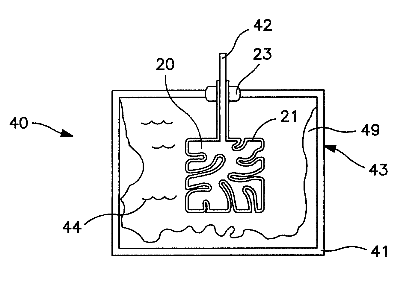
[0049]The ability to form a cathode in accordance with the present invention was demonstrated. Initially, a sheet of grade #1 titanium (thickness of 120 μm, Sigma-Aldrich) was cut into two squares having a width of 10.0 millimeters for use as the metal substrates. The squares were roughened with No. 220 sand paper to remove all the visible stains and discoloration on the surface. Thereafter, a 15-mm long tantalum wire was spot-welded to the center of an upper edge of the square to facilitate subsequent processing and electrical measurements. These samples were then degreased in soap water in an ultrasonic bath for 60 minutes, rinsed 5 times in deionized water, and then vacuum dried at a temperature of 50° C. and gauge pressure of −26″ Hg for more than 2 hours.

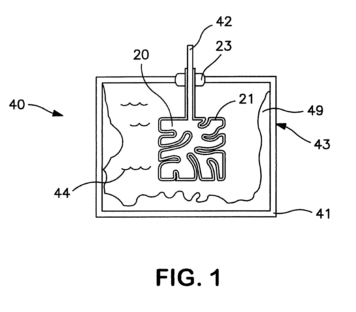
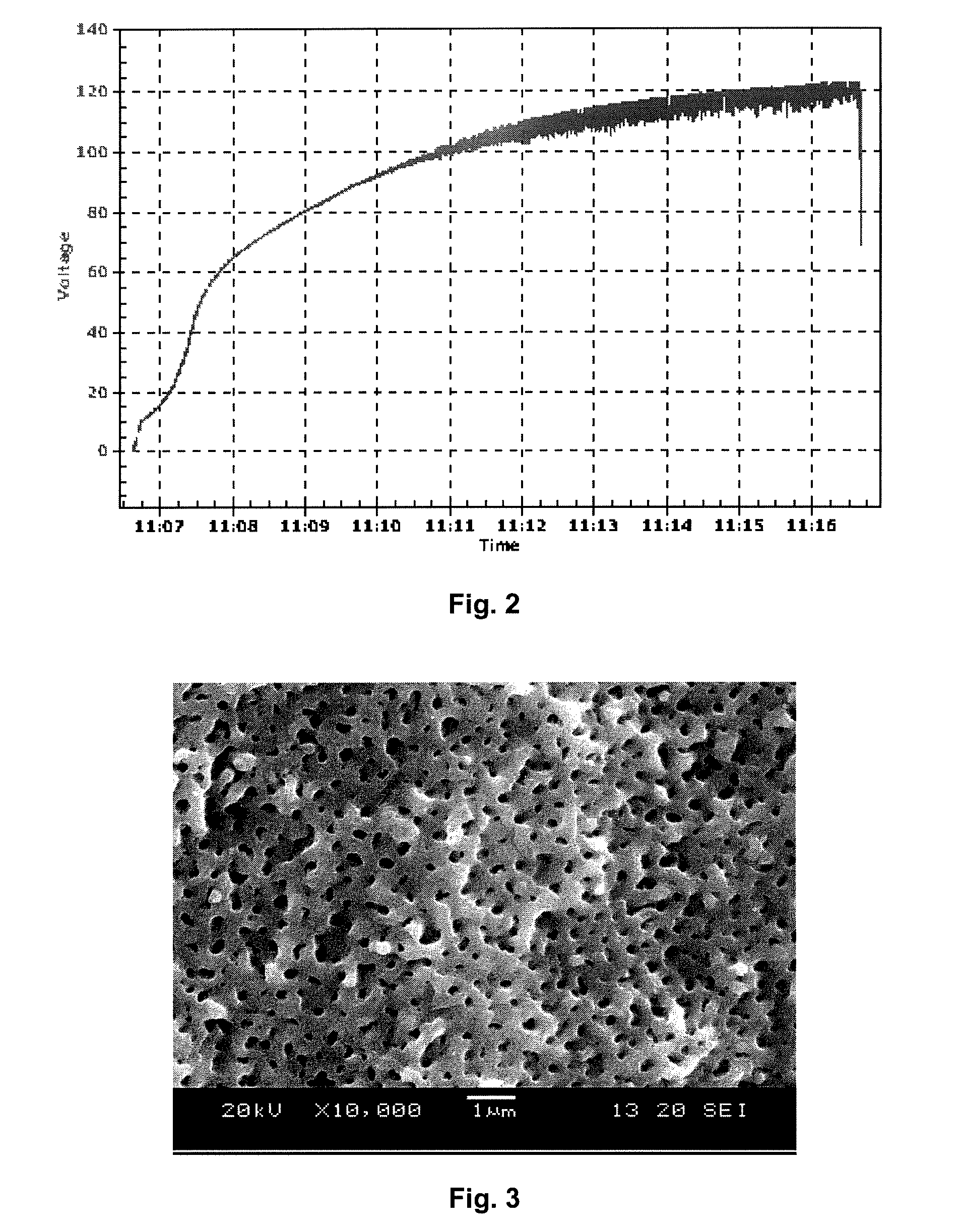
[0050]To form the porous surface, the two samples were dipped into a solution of 1.0 M H2SO4. An electrochemical cell was created using a titanium sample as prepared above as the anode and a piece of platinum gauze as the catho...

example 2

[0054]Two (2) titanium samples were prepared as described in Example 1, except that the mesh structure was modified prior to application of the PEDT coating by heat treating in an argon atmosphere at a temperature of 750° C. for 30 minutes. The resulting structure is shown in FIG. 4. As indicated, the surface remained highly porous, although pores larger than 1,000 nanometers (1 μm) did occur at certain locations. The specific cathode capacitance of the samples was determined to be 16.44 mF / cm2 and 33.50 mF / cm2.

example 3

[0055]Two (2) titanium samples were prepared as described in Example 1, except that the mesh structure was modified prior to application of the PEDT coating by heat treating in an argon atmosphere at a temperature of 750° C. for 30 minutes in the presence of 1 gram of magnesium turnings. The resulting structure is shown in FIG. 5. The color of the surface changed from gray to black, which was possibly due to the formation of a titanium-magnesium alloy. Regardless, as shown, the surface remained highly porous and ordered. The specific cathode capacitance of the samples was determined to be 24.80 mF / cm2 and 21.05 mF / cm2.


PUM

PropertyMeasurementUnit
average sizeaaaaaaaaaa
sizeaaaaaaaaaa
thicknessaaaaaaaaaa

Abstract

A porous substrate for use in a wide variety of applications, such as wet capacitors, is provided. The substrate is formed by subjecting a metal substrate to a voltage while in solution to initiate anodic formation of an oxide film. Contrary to conventional anodization processes, however, the newly created oxide quickly breaks down to once again expose the metal surface to the electrolytic solution. This may be accomplished in a variety of ways, such as by raising the voltage of the solution above a critical level known as the “breakdown voltage”, employing a corrosive acid in the solution that dissolves the oxide, etc. Regardless of the mechanism employed, the nearly simultaneous process of oxide growth / breakdown results in the formation of a structure having pores arranged at substantially regular intervals. The resulting structure is highly porous and can exhibit excellent adhesion to electrochemically-active materials and stability in aqueous electrolytes.

Description

BACKGROUND OF THE INVENTION[0001]Wet capacitors are increasingly being used in the design of circuits due to their volumetric efficiency, reliability, and process compatibility. Wet capacitors typically have a larger capacitance per unit volume than certain other types of capacitors, making them valuable in high-current, high power and low-frequency electrical circuits. One type of wet capacitor that has been developed is a wet electrolytic capacitor that includes a valve metal anode, a cathode, and a liquid electrolyte. The unit cell voltage in this type of capacitor is generally higher due to the formation of a dielectric metal oxide film over the anode surface. Wet electrolytic capacitors tend to offer a good combination of high capacitance with low leakage current. Another type of wet capacitor is a wet symmetric capacitor in which the anode and cathode are similar in terms of structure and composition. The unit cell voltage in this type of capacitor is generally low due to the ...

Claims


Application Information

Patent Timeline
Patent Type & Authority Patents(United States)
IPC IPC(8): H01G9/04
CPCH01G9/0032H01G9/048H01G9/0425H01G9/145H01G9/004H01G9/042
Inventor NING, GANGSEBALD, ZEBBIE LYNNRAWAL, BHARAT
Owner KYOCERA AVX COMPONENTS CORP
Learn More