Fuel cell

a fuel cell and fuel cell technology, applied in the field of fuel cells, can solve the problems of insufficient distribution and supply of reaction gas, adverse effects of hydrophobic finishing, and insufficient supply of water

Inactive Publication Date: 2000-07-04
SANYO ELECTRIC CO LTD
View PDF16 Cites 93 Cited by
  • Summary
  • Abstract
  • Description
  • Claims
  • Application Information

AI Technical Summary

Benefits of technology

To achieve the above objects, the fuel cell of the present invention is applied with a current collector having a new structure. As a result, cell characteristics, such as cell voltage, does not decrease over time.
In other words, because the hydrophilic areas let out water and water does not stay near the interface between an electrode and a current collector, reaction gas is supplied without obstacle. When this current collector having hydrophilic areas is applied to a polymer electrolyte fuel cell, water is supplied through the hydrophilic areas with reliability so that a polymer electrolyte membrane is efficiently humidified.
Because reaction product water tends to stay near a cathode of any types of fuel cells, a current collector of the present invention applied to a cathode achieves a profound effect.

Problems solved by technology

As a result, the hydrophobic finishing affects adversely and the reaction gas is not sufficiently distributed and supplied.
In particular, when the current collectors are applied to a polymer electrolyte fuel cell, water is not sufficiently supplied to a polymer electrolyte membrane so that the polymer electrolyte membrane is dried.

Method used


Image

  • Fuel cell
  • Fuel cell
  • Fuel cell

Examples


embodiment 1

Entire Structure of Polymer Electrolyte Fuel Cell

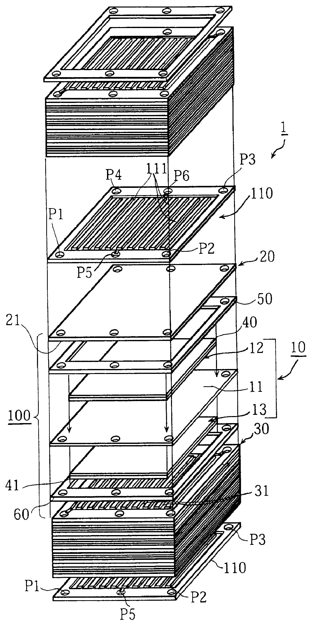
FIG. 1 is an assembly drawing of a structure of the main part of the polymer electrolyte fuel cell 1 (hereinafter referred to as the fuel cell 1).

The fuel cell 1 is composed of a plurality of basic units 100 which are laminated, with cooling plates 110 being each inserted between the basic units. The basic units 100 and the cooling plates 110 are sandwiched between two insulated end plates which are not shown in the drawing. Note that the number of basic units 100 is adjusted according to intended voltage output.

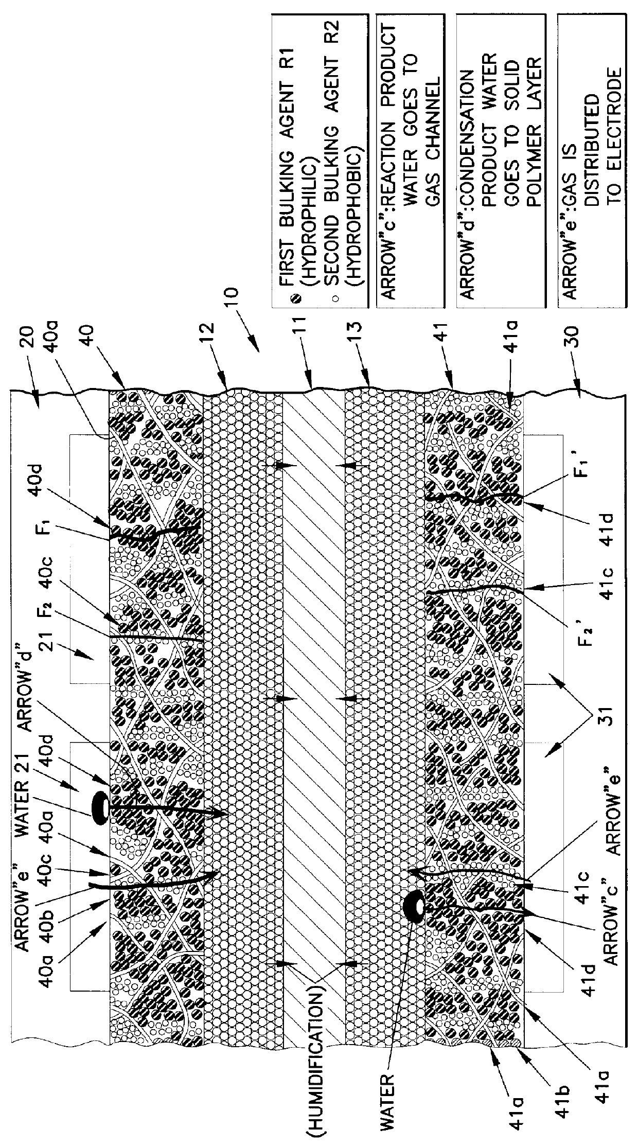
This basic unit 100 includes: cell 10 including polymer electrolyte membrane 11 which is an electrolyte layer, anode 12, and cathode 13, where the anode 12 and the cathode 13 are respectively placed on the center of surfaces of the polymer electrolyte membrane 11; a pair of separator plates 20 and 30, where the separator plate 20 is provided with a plurality of anode gas channels 21 (the gas channels 21 cannot be seen in FIG. ...

experiment 1

Cathode-side current collectors "A" and "B" of carbon paper processed as shown in Table 2 (FIG. 11) based on this embodiment and cathode-side current collector "C" for comparison are produced. Fuel cells for experiment (experiment fuel cells) including the current collectors "A" and "B" having the above structure and a fuel cell for comparison (a comparison fuel cell) including the current collector "C" are produced.

Members, except for the cathode-side current collector, constructing each fuel cell are produced under the conditions below.

Electrodes (an anode and a cathode) are made of platinum carbon (Pt / C), NAFLON.RTM., and PTFE (weight ratio is 67.9:2.1:30) using a known sheet forming method.

A polymer electrolyte membrane is made of NAFLON.RTM.. The polymer electrolyte membrane and the electrodes are crimped using the hot press method (temperature is 150.degree. C., 70 kg / cm.sup.2, process time is 90 seconds), with the layer and electrodes contacting each other, to produce a cell....

experiment 2

The following is a description of change in cell characteristics due to various cathode gas humidification temperatures, 63.degree. C., 73.degree. C., 78.degree. C., and 80.degree. C. under the following operating conditions.

(Operating Conditions)

cell temperature: 80.degree. C.

current density: 0.5 A / cm.sup.2

utilization factor of hydrogen gas: 50%

utilization factor of oxygen: 20%

Electrodes of fuel cells used for this experiment are made of paste whose composition is (Pt / C) NAFLON.RTM. (weight ratio=100 / 15) using the screen printing method, unlike the current collectors "A" and "B". NAFLON.RTM. solution of 0.5 g / cm.sup.2 is sprayed on surfaces of the electrodes to produce Nafion layers. The electrodes with the NAFLON.RTM. layers are subjected to the hot pressing to form a cell structure element. The structures, except for the electrodes, of the fuel cells are the same as those of Experiment 1.

FIG. 5 shows experiment results. As shown in FIG. 5, in the case of the experiment fuel cell ...


PUM

PropertyMeasurementUnit
temperatureaaaaaaaaaa
particle diameteraaaaaaaaaa

Abstract

A current collector includes a thin porous substrate and a hydrophilic material, where the hydrophilic material is provided to holes of the thin porous substrate or surfaces of skeleton elements of the porous substrate so that hydrophilic areas formed by the hydrophilic material successively pass through the thin porous substrate between both surfaces of the thin porous substrate. In the current collector, water is let out through the hydrophilic areas and does not stay on an interface between an electrode and the current collector so that reaction gas is not hampered and is supplied, unlike a conventional current collector. When the current collector is applied to a polymer electrolyte fuel cell, water is supplied with reliability through the hydrophilic areas to a polymer electrolyte membrane so that the polymer electrolyte membrane is effectively humidified. The current collector applied to a cathode achieves a profound effect because reaction product water tends to stay around a cathode of any types of fuel cells. The current collector also includes gas flow paths which are surrounded by particles of a hydrophobic material and pass through the thin porous substrate between both surfaces of the thin porous substrate. As a result, gas permeability of the current collector is maintained with reliability.

Description

(1) Field of the InventionThe present invention relates to a fuel cell and in particular to a technique for improving a current collector.(2) Related ArtFuel cells directly take out electric power of chemical energy of fuel, such as hydrogen, using reverse reaction of water electrolysis, which is the basic principle of fuel cells.Fuel cells are divided into several types in terms of methods of realizing this principle. General fuel cells are alkali type, polymer electrolyte type, phosphoric acid type, fused carbonate electrolyte type, and high temperature solid electrolyte type.The following description concerns a polymer electrolyte fuel cell, one type of the fuel cells. The polymer electrolyte fuel cell has a lamination structure which includes: a cell composed of an anode, a cathode, and a polymer electrolyte membrane therebetween; a pair of separator plates with ribs which sandwiches the cell; a pair of current collectors which are each inserted between one of the separator plat...

Claims


Application Information

Patent Timeline
Patent Type & Authority Patents(United States)
IPC IPC(8): H01M8/10H01M8/02H01M8/24H01M8/04H01M4/66H01M8/06
CPCH01M8/023H01M8/0241H01M8/0247H01M8/0258H01M8/1004H01M8/04119H01M8/04156H01M8/242H01M2300/0082Y02E60/521H01M8/0267H01M8/2483Y02E60/50H01M8/02H01M8/24
Inventor TANIGUCHI, SHUNSUKEHAMADA, AKIRAMIYAKE, YASUOKANEKO, MINURO
Owner SANYO ELECTRIC CO LTD
Why Eureka
Try Eureka