Method and apparatus for video buffer verifier underflow and overflow control

a buffer verifier and video technology, applied in the field of video buffer verifier underflow and overflow control, can solve the problems of picture-level overflow control not being able to effectively prevent vbv buffer overflow, buffer overflow, buffer overflow, etc., to improve the quality of video, improve the prevention of panic mode encoding, and improve the effect of underflow and overflow prevention

Inactive Publication Date: 2004-06-03
STMICROELECTRONICS ASIA PACIFIC PTE
View PDF2 Cites 20 Cited by
  • Summary
  • Abstract
  • Description
  • Claims
  • Application Information

AI Technical Summary

Benefits of technology

The present invention aims to improve video encoding by introducing additional picture and slice level controls. This will help prevent panic mode encoding, prevent underflow and overflow, and enhance video quality.

Problems solved by technology

The technical problem of this patent text is to provide a solution for improving the efficiency and accuracy of infrared temperature measurement for non-contact type thermometers, especially for small measurement targets.

Method used


Image

  • Method and apparatus for video buffer verifier underflow and overflow control
  • Method and apparatus for video buffer verifier underflow and overflow control
  • Method and apparatus for video buffer verifier underflow and overflow control

Examples


Embodiment Construction

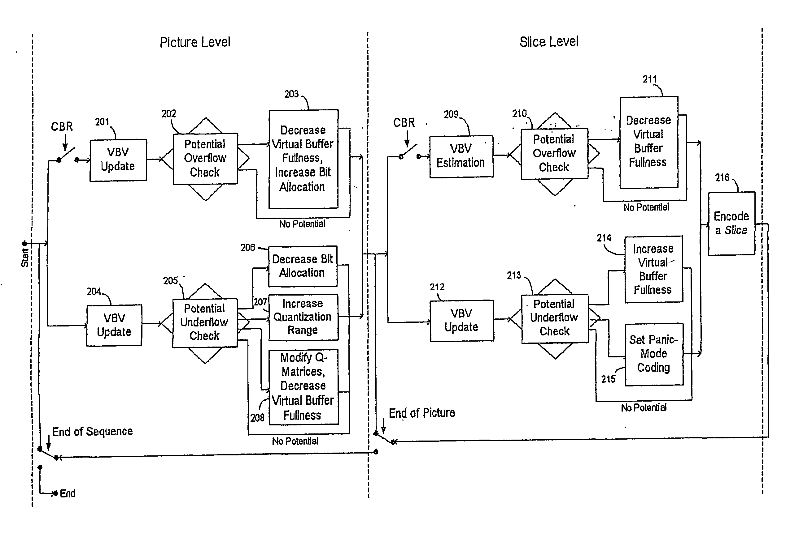
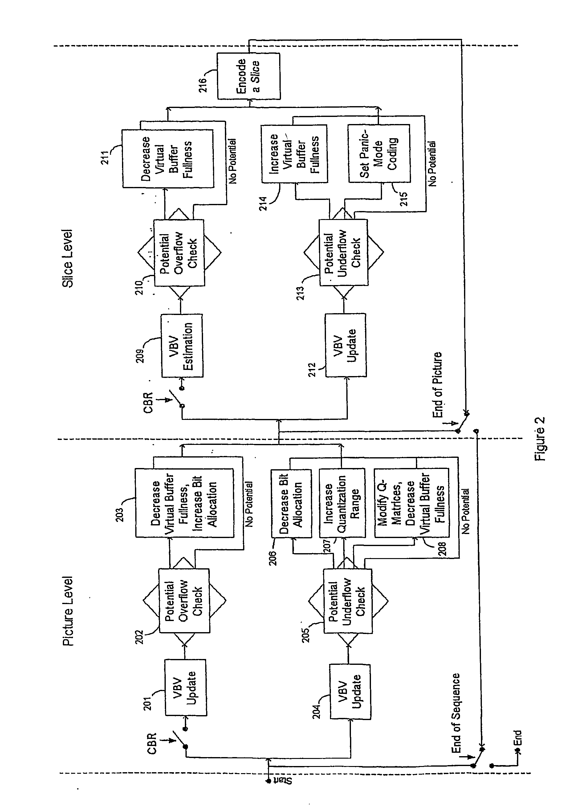
[0107] In a particular embodiment, the present invention is directed to the prevention of VBV underflow and overflow during MPEG-2 video encoding.

[0108] Underflow Control

[0109] Picture Level:

[0110] The basic step in underflow and panic mode coding prevention is the reducing of the target bits T when necessary. The target bits T in equation (5) are replaced by (T+PM) where PM is defined as the preventive margin to take care of the additional bits that might be used to encode the next picture.

[0111] Apart from adjusting the target bits T, additional picture level prevention steps can be used.

[0112] A further preventive step is to increase the range of the quantization-step (Q-step) to be used, for example the MPEG-2 non-linear quantization scheme allows the quantization-step to go up to 112. This is used when a potential of panic mode occurrence is detected.

[0113] A still further preventive step which may be optionally employed is to use customised quantization matrices which are of h...


PUM


Abstract

A method and apparatus for Video Buffer Verifier (VBV) underflow and overflow control. A combination of picture and slice level control is used in the method and apparatus. Improved prevention of overflow and panic mode encoding is achieved by means of adjustment of the virtual buffer-fullness which allows the quantization-step to have an improved response to the buffer-fullness at both high and low critical levels. The use of a non-linear quantization scheme and customised quantization matrices also provide improved prevention of panic mode encoding. The slice level control also reduces the computation complexity compared to the macroblock level control.

Description


Claims


Application Information

Patent Timeline
Owner STMICROELECTRONICS ASIA PACIFIC PTE
Why Eureka
Try Eureka