Device and a method for calibration of an industrial robot

a technology for industrial robots and calibration methods, applied in process and machine control, program control, instruments, etc., can solve the problems of mounting errors, inclinometers that must be mounted on the planes of reference of robots with very high precision, and large number of sources of errors when attaching inclinometers to robots, so as to reduce the number of sources of errors

Inactive Publication Date: 2002-07-16
ABB (SCHWEIZ) AG
View PDF4 Cites 82 Cited by
  • Summary
  • Abstract
  • Description
  • Claims
  • Application Information

AI Technical Summary

Benefits of technology

is to achieve a device for calibration of an industrial robot reducing the number of so

Problems solved by technology

A problem with said method of calibration is that the inclinometer must be mounted on the planes of reference of the robot with a very high precision.
This way of attaching the inclinometer to the robot includes a large number of sources of error.
Examples of sources of error are mounting errors between the adapter plate and the plane of reference of the robot, mount

Method used


Image

  • Device and a method for calibration of an industrial robot
  • Device and a method for calibration of an industrial robot
  • Device and a method for calibration of an industrial robot

Examples


first embodiment

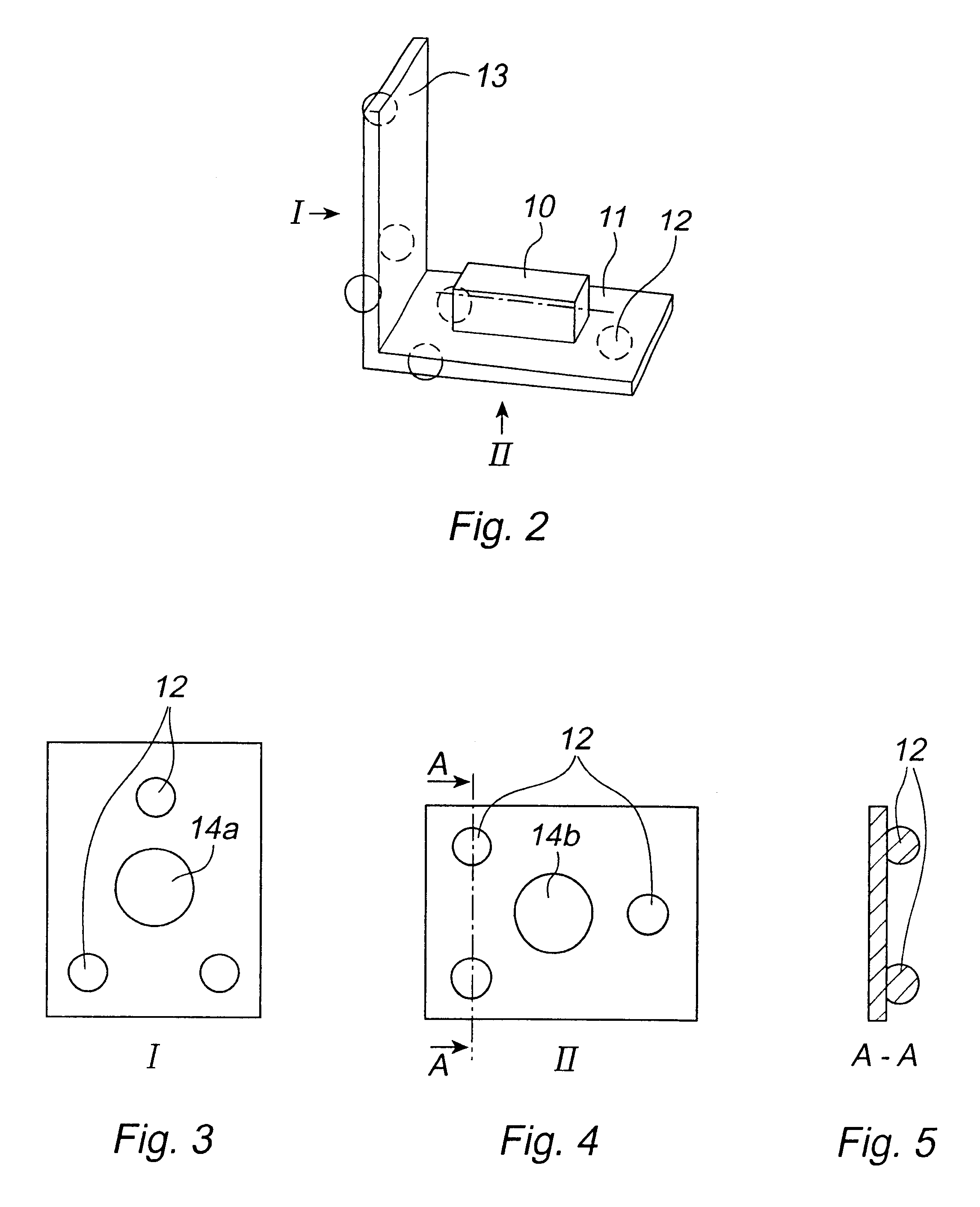
FIG. 2 shows a calibration device according to the invention.

FIG. 3 shows a side view of the calibration device in FIG. 2.

FIG. 4 shows a view from below of the calibration device in FIG. 2.

FIG. 5 shows a cross-sectional view of the calibration device along the line A--A in FIG. 3.

FIG. 6 shows a plate having three grooves intended to be connected to three contact elements of the calibration device.

FIG. 7 shows a plate having a groove, a triangular prism, and a surface intended to be in contact with three contact elements of the calibration device.

FIG. 8 shows a plate having two grooves and a surface intended to be in contact with three contact elements.

FIG. 9 shows a cross-section of the calibration device along the line B--B in FIG. 7.

second embodiment

FIG. 10 shows a calibration device according to the invention which has two angle measuring devices arranged in different angles.

third embodiment

FIG. 11 shows a calibration device according to the invention.

FIG. 12 shows a further embodiment of the calibration device according to the invention.


PUM


Abstract

A device for calibration of an industrial robot, which calibration device is adapted for being in contact during the calibration with at least one plane of reference arranged on the robot, the calibration device includes an angle measuring member arranged for measuring an angle relative to the vertical line. The device further comprises two contact elements each having a curved surface, and the contact elements are arranged for being in contact with the plane of reference.

Description

The present invention relates to a device for calibration of an industrial robot, which calibration device is adapted for being in contact during the calibration with at least one plane of reference arranged on the robot, the device comprising an angle measuring member arranged for measuring an angle relative to the vertical line.The present invention further relates to an industrial robot comprising at least two links moveably attached to each other by a joint, at least one plane of reference arranged on any of the links, and a calibration device adapted for being in contact with the plane of reference during the calibration.The present invention also relates to a method for calibration of an industrial robot.PRIOR ARTAn industrial robot can be viewed as a chain of stiff links. Two adjacent links are joined with each other so that they either are rotatable relative to each other around a rotational axis or linearly displaceable relative to each other. The first link in the chain is...

Claims


Application Information

Patent Timeline
IPC IPC(8): B25J9/16G01C9/00G01C25/00B25J9/10B25J9/22
CPCB25J9/1692G01C9/00G01C25/00G05B2219/39024G05B2219/39026G05B2219/39027G05B2219/39058G05B2219/40597
Inventor BROG.ANG.RDH, TORGNYJERREG.ANG.RD, HENRIKROBERTSON, ALECSLOCUM, ALEXANDERWILLOUGHBY, PATRICK
Owner ABB (SCHWEIZ) AG
Why Eureka
Try Eureka