System and method for dividing flow

a technology of flow and system, applied in the field of system and method of gas box, can solve problems such as inaccuracy of techniques

Inactive Publication Date: 2002-07-16
MKS INSTR INC
View PDF18 Cites 97 Cited by
  • Summary
  • Abstract
  • Description
  • Claims
  • Application Information

AI Technical Summary

Problems solved by technology

Otherwise, the technique may not be as accurate when the upstream pressure needs to be kept lower (e.g., less than 15 PSIA) for safety or other reasons.

Method used


Image

  • System and method for dividing flow
  • System and method for dividing flow
  • System and method for dividing flow

Examples


Embodiment Construction

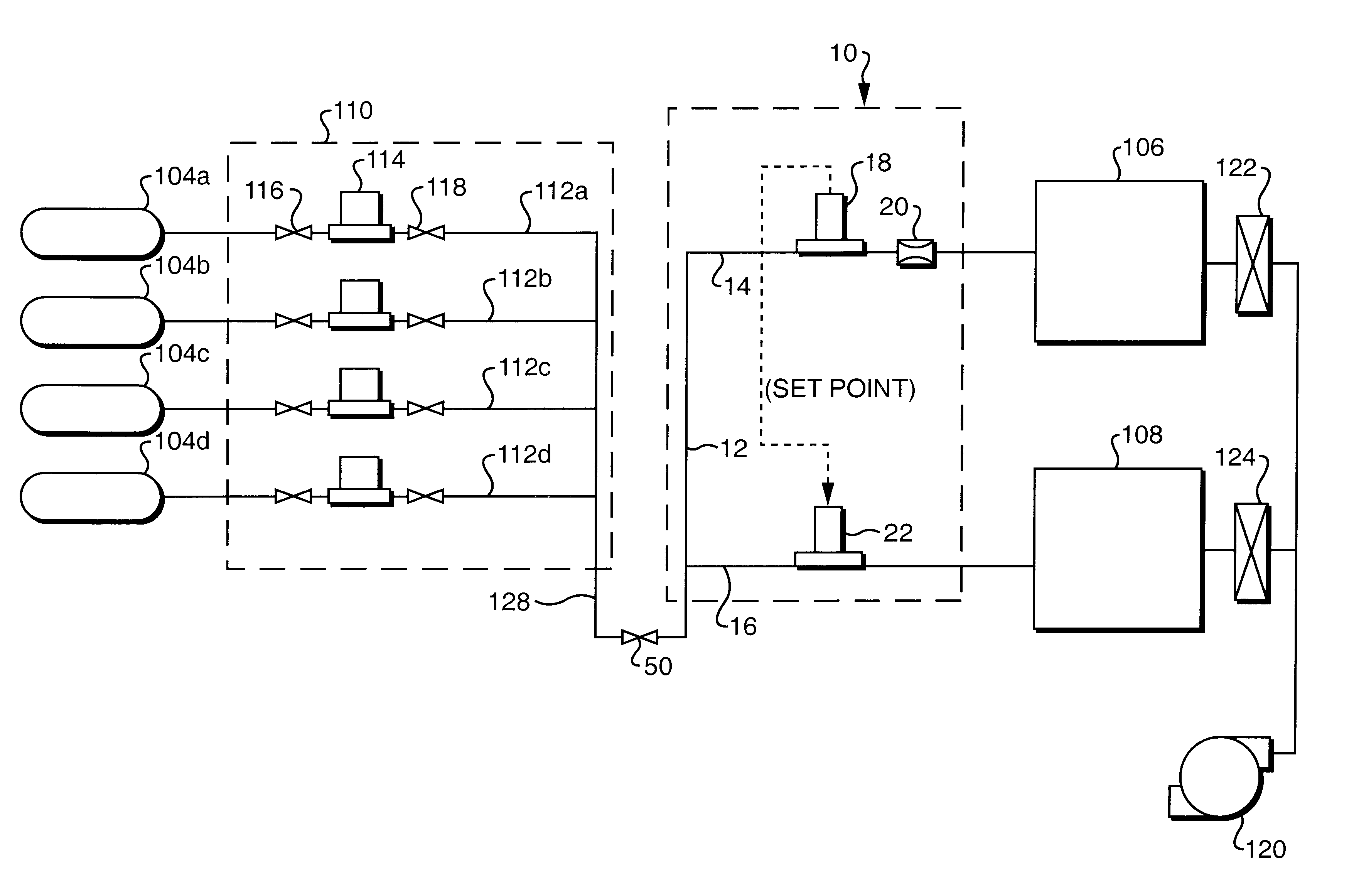
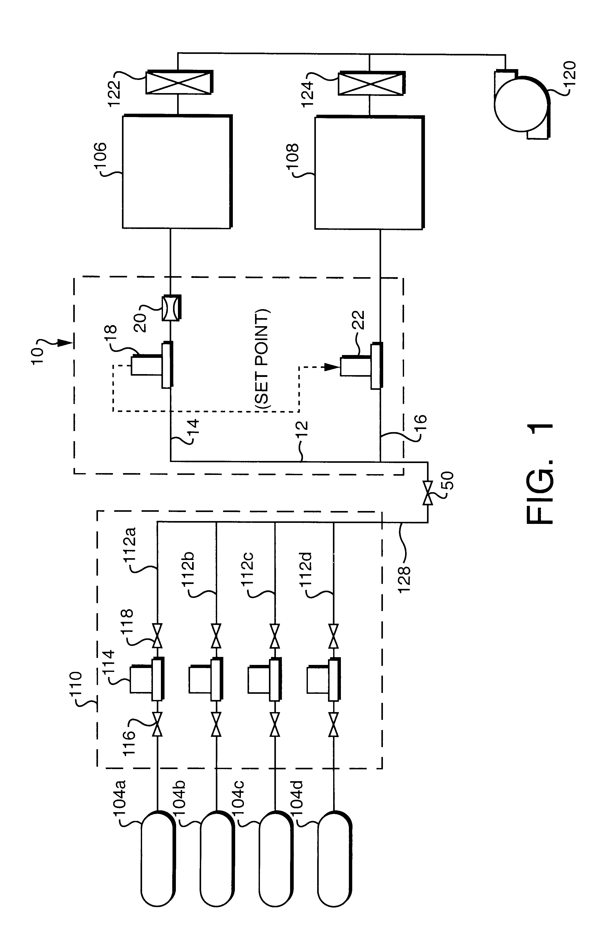
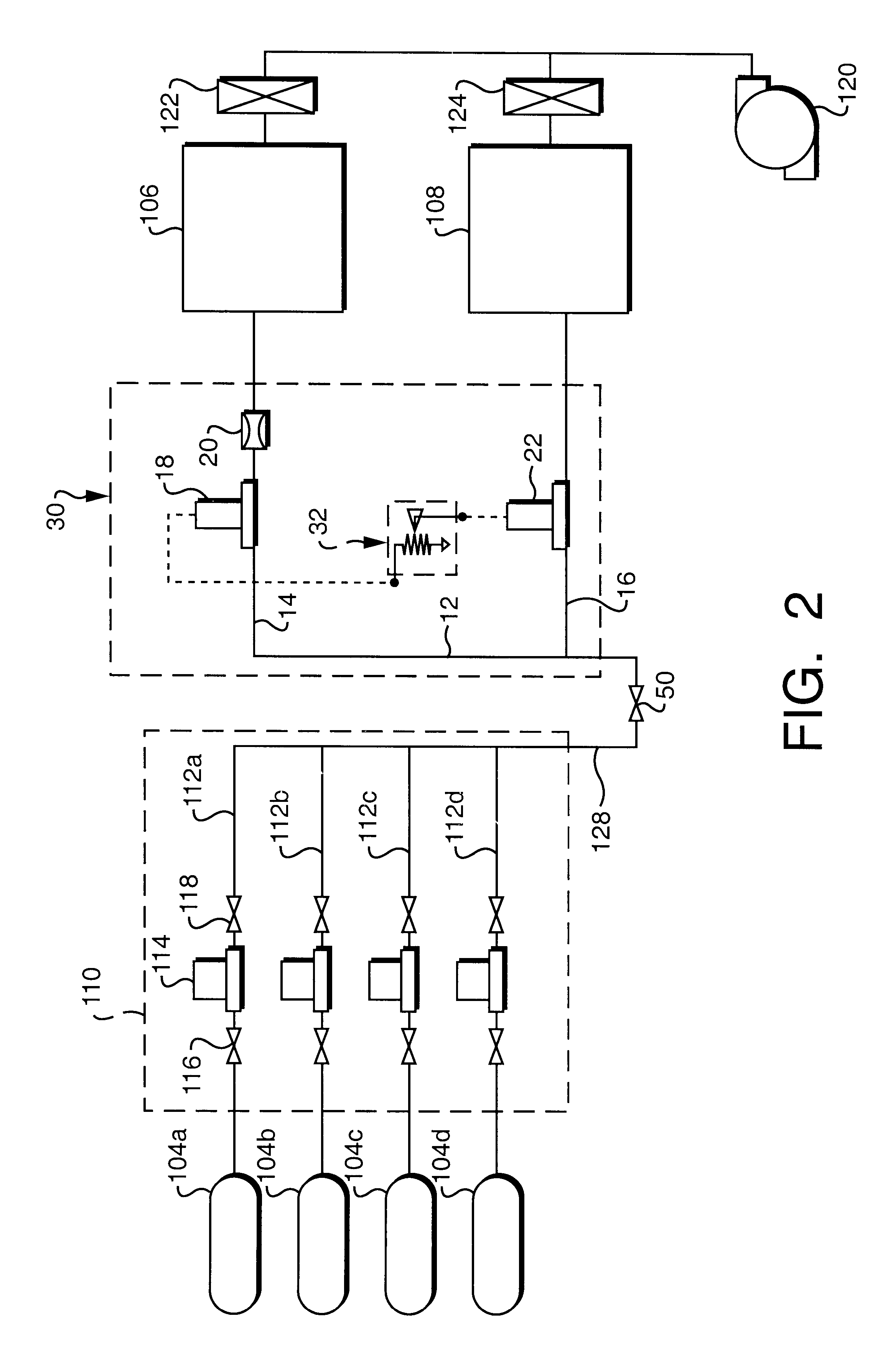
Referring to FIG. 1, the present disclosure provides a system and method of dividing flow between at least two flow paths. The system and method are particularly intended for use with gas metering systems for delivering contaminant-free, precisely metered quantities of process and purge gases to semiconductor process chambers. The presently disclosed system and method provide the benefit of dividing a single flow of gas into two or more secondary flows of known, precise values, without requiring a relatively high upstream pressure.

Referring first to FIG. 4, however, a system 100 for dividing flow according to the prior art is shown. The system 100 is incorporated in a gas metering system 102 that receives multiple gases, including both process gases and a purge gas, from gas supplies (e.g., gas tanks) 104a, 104b, 104c, 104d and then precisely meters the gases to two process chambers 106, 108 (alternatively, the gases can be metered to different injectors or areas of a single process...


PUM


Abstract

A system for dividing a single flow of gas into two or more secondary flows of known, precise values, without requiring a high upstream pressure. The system includes an inlet for receiving the single gas flow, and first and second flow lines connected to the inlet. A mass flow meter measures gas flow through the first line and provides a signal indicative of the measured flow rate. A restrictor restricts gas flow through the first line to a desired flow rate, and has a smallest cross-sectional flow area selected to provide an upstream pressure high enough to allow the mass flow meter to operate properly and lower than a predetermined upper pressure limit. A mass flow controller receives the signal indicative of the measured flow rate from the mass flow meter and maintains a flow rate through the second line based on the signal.

Description

FIELD OF DISCLOSUREThe present disclosure relates generally to semiconductor processing equipment and, more particularly, to a gas box for delivering contaminant-free, precisely metered quantities of process gases to semiconductor process chambers. Even more particularly, the present disclosure relates to a system and method for dividing flow from a single gas box among multiple process chambers.BACKGROUND OF DISCLOSUREThe fabrication of semiconductor devices often requires the careful synchronization and precisely measured delivery of as many as a dozen gases to a process chamber. Various recipes are used in the fabrication process, and many discrete processing steps where a semiconductor device is cleaned, polished, oxidized, masked, etched, doped, metalized, etc., can be required. The steps used, their particular sequence and the materials involved all contribute to the making of particular devices.Accordingly, wafer fabrication facilities are commonly organized to include areas ...

Claims


Application Information

Patent Timeline
Patent Type & Authority Patents(United States)
IPC IPC(8): G05D11/13G05D11/00H01L21/02G05D7/06
CPCG05D11/132Y10T137/0363Y10T137/2529Y10T137/2531Y10T137/2657H01L21/02
Inventor TAYLOR, MATTHEW THOMASHALLAHAN, JOHN CHRISTOPHERCLARK, WILLIAM R.
Owner MKS INSTR INC
Why Eureka
Try Eureka