Stamping device

a technology of stamping device and stamping pattern, which is applied in the direction of printing press, printing apparatus, etc., can solve the problems of inability to accurately position the pattern on the surface to be imprinted, the prior art hand stamping device having legends such as words and numbers is difficult to use, and the pattern is difficult to precisely position

Inactive Publication Date: 2002-07-23
DALE LOOKHOLDER
View PDF7 Cites 7 Cited by
  • Summary
  • Abstract
  • Description
  • Claims
  • Application Information

AI Technical Summary

Benefits of technology

The thrust of the present invention is to provide an improved hand-held ink stamp in which both the mounting block and the imprinting element that is removably affixed thereto without the use of adhesives are substantially transparent so that the indicia formed on the imprinting element can be seen clearly and precisely positioned on the surface to be imprinted.
It is an object of the present invention to provide a novel hand stamp and method of making the same which is of an elegantly simple construction that includes a substantially transparent acrylic mounting block to which a substantially transparent printing element is removably affixed without the use of adhesives. With this construction, when the device is used, the indicia formed on the printing element can be clearly viewed through the mounting block, and the printing surface can be clearly viewed through the printing element.
Another object of the invention is to provide a hand stamp of the aforementioned character in which the sides of the mounting block are provided with finger gripping means so that the stamp can be conveniently gripped by the user.

Problems solved by technology

However, because the pattern-bearing surface cannot be seen through the stamp supporting block or handle it is virtually impossible to precisely position the pattern on the surface to be imprinted.
Similarly, prior art hand stamp devices having indicia in the form of legends such as words and numbers are difficult to use because the user cannot see the indicia and therefore cannot accurately position it on the surface to be imprinted.
However, because the imprinting element itself is not transparent, precise positioning of the indicia on the imprinting element remains difficult.
However, like the Sastre device, the printing element itself is not transparent.

Method used


Image

  • Stamping device
  • Stamping device
  • Stamping device

Examples


Embodiment Construction

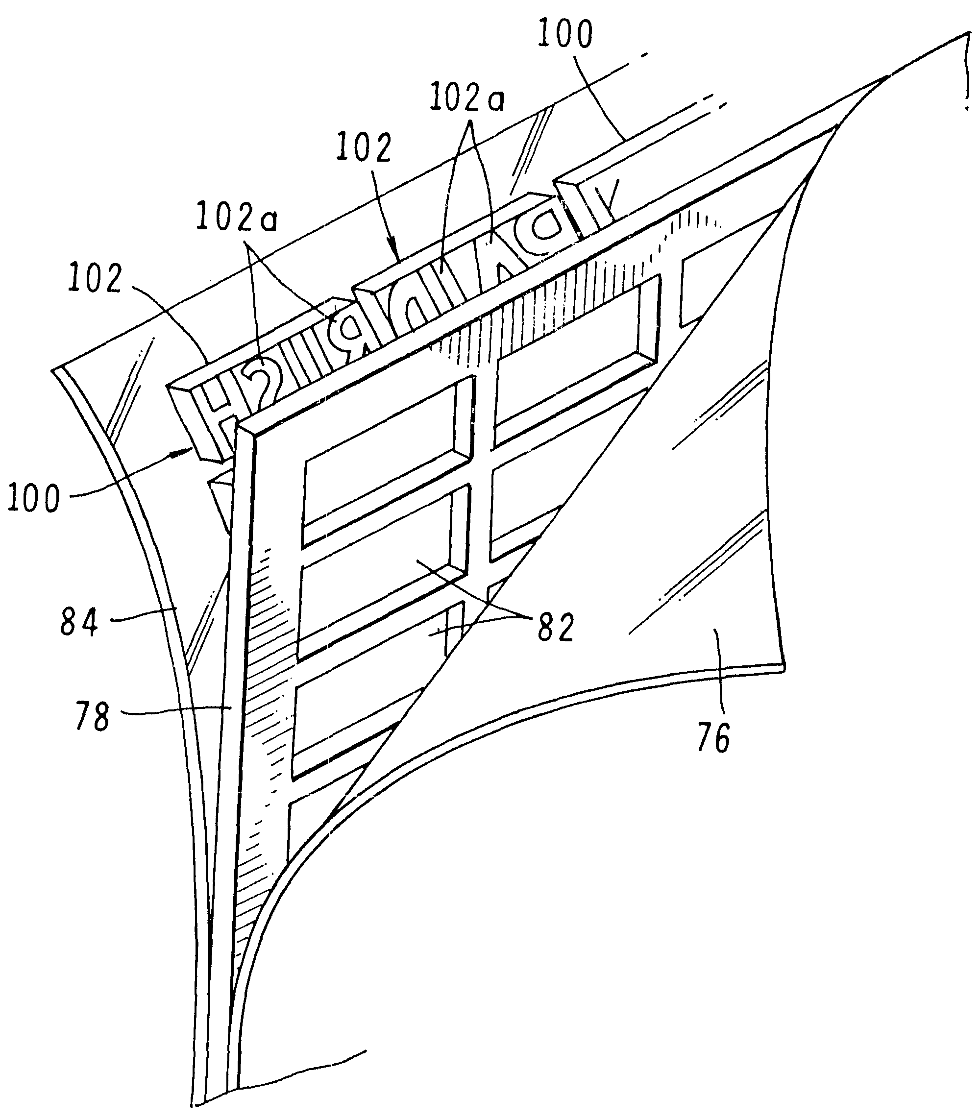
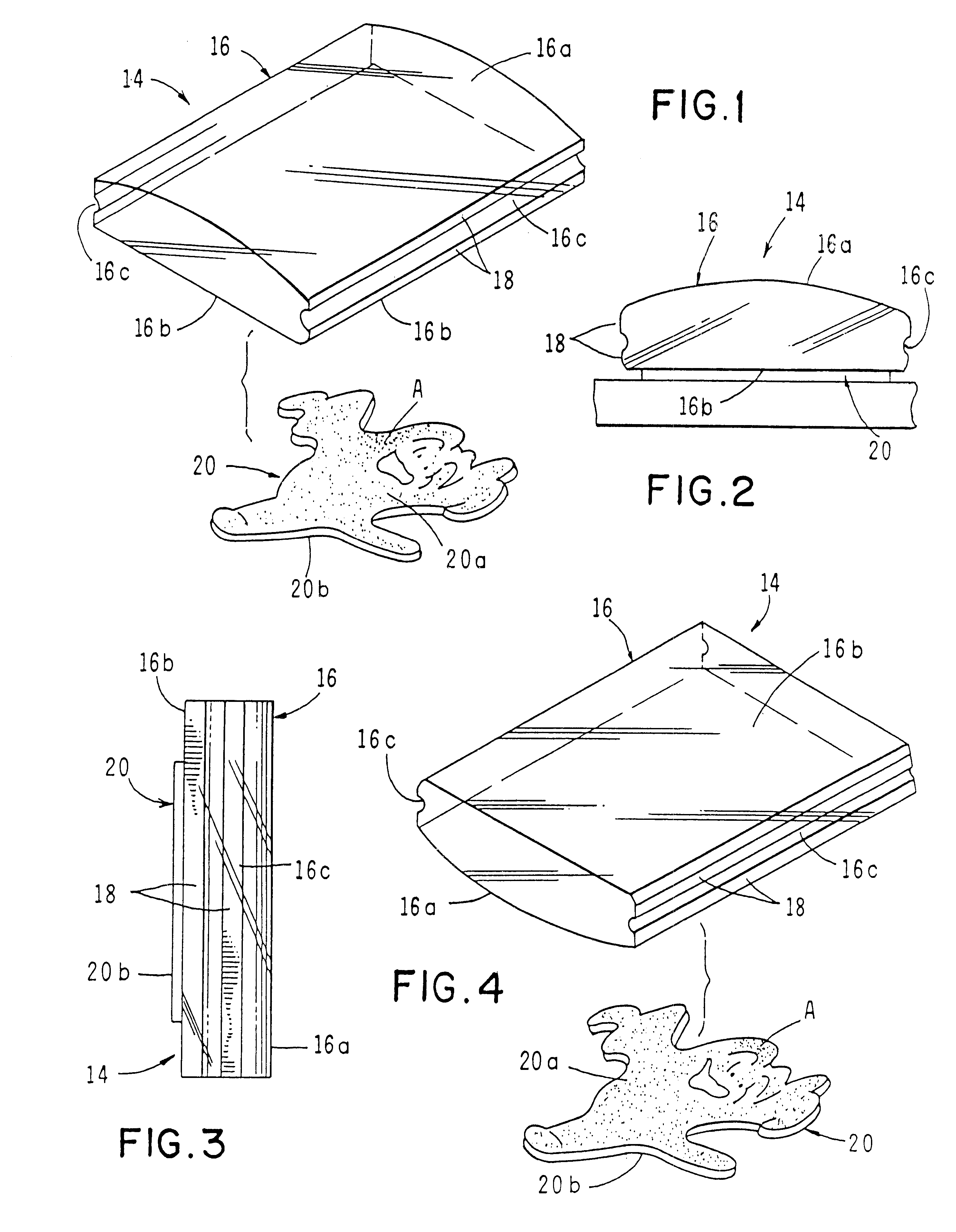
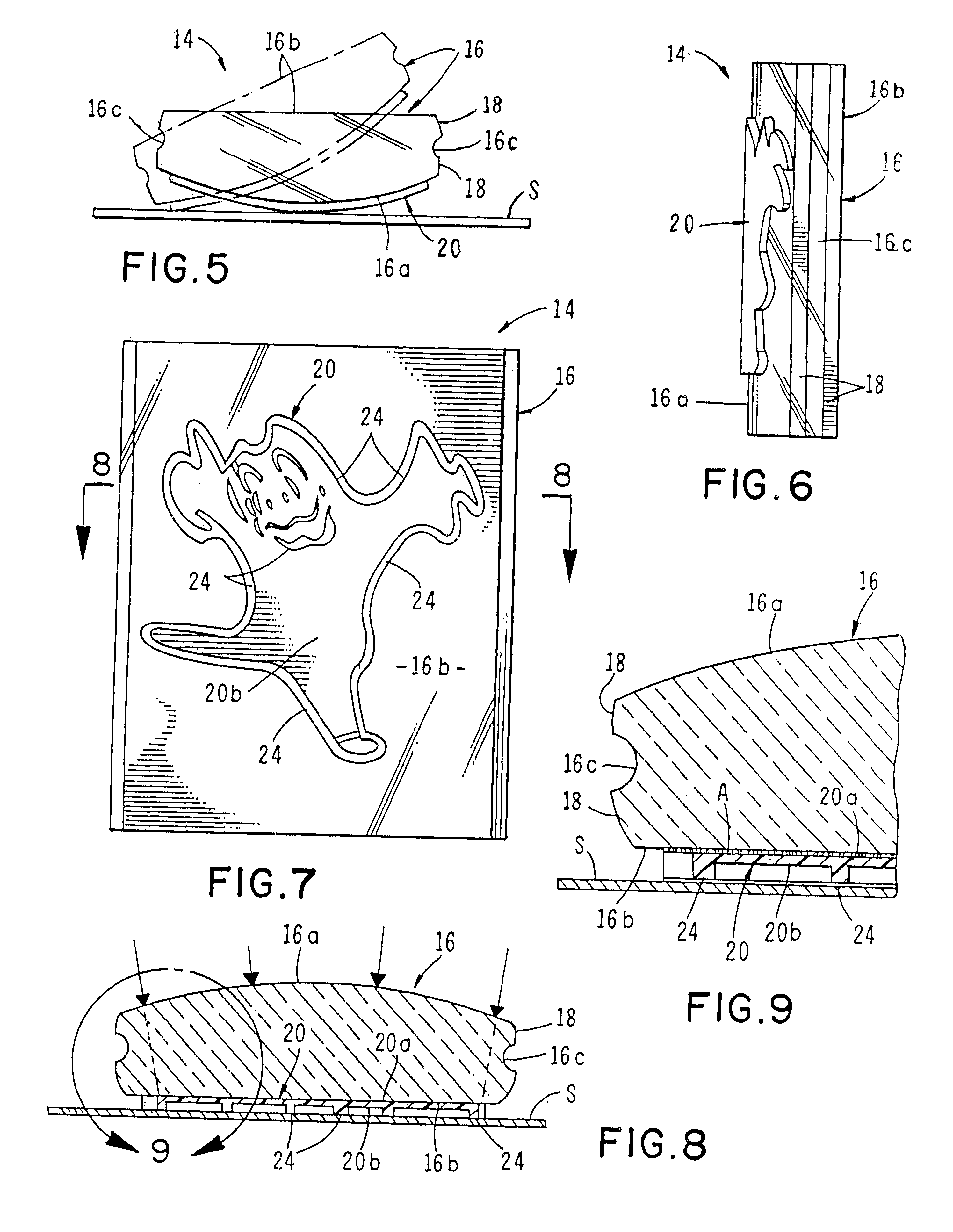
Referring to the drawings and particularly FIGS. 1 through 3, one form of the stamping device of the invention is there illustrated and generally designated by the numeral 14. The device here comprises a substantially transparent, rigid, plastic mounting block 16 having a mirror polished, convex top surface 16a, a generally planar, mirror polished bottom surface 16b, and spaced-apart sides 16c. As best seen in FIGS. 1 and 2 each of the spaced-apart sides 16c is provided with gripping means shown here as finger gripping portions 18. Mounting block 16 can be formed of various plastics but a clear acrylic has proven satisfactory.

In the form of the invention shown in FIGS. 1, 2, and 3, a substantially transparent imprinting element or die 20 is removably affixed to bottom surface 16b in the manner indicated in FIGS. 2 and 3. Imprinting element 20 is preferably formed of a photopolymer such as a liquid polyester that will polymerize when exposed to ultraviolet light. Element 20 is resili...


PUM


Abstract

A hand-held stamping device and the method of making same that includes a substantially transparent acrylic mounting block to which a substantially transparent printing element is removably affixed without the use of adhesives. When the device of the invention is used, the indicia formed on the printing element can be clearly viewed through the mounting block, and the printing surface can be clearly viewed through the printing element. This enables precise positioning of the indicia on the surface to be printed. The device includes both a convex surface and a planar surface to which the printing element can be removably affixed. When the printing element is affixed to the planar surface, the indicia on the printing element, when viewed through the convex surface, is magnified.

Description

FIELD OF THE INVENTIONThe present invention relates generally to hand stamping devices and the method of making same. More particularly, the invention concerns a novel hand stamping apparatus having a substantially transparent, hand-held mounting block to which a substantially transparent printing element or die can be removably affixed without the use of adhesives. In using the device the printing element can be clearly viewed through the transparent mounting block and the surface to be imprinted can be viewed through the printing element so that the indicia formed on the printing element can be precisely positioned relative to the surface to be imprinted.DISCUSSION OF THE INVENTIONHand stamp devices of many different configurations have been suggested in the past. The classic hand stamp comprises a rubber stamp die that is fixedly mounted on a wooden block to which a bulb shaped wooden handle is attached. Such hand stamps are traditionally used with an ink pad which applies ink to...

Claims


Application Information

Patent Timeline
Patent Type & Authority Patents(United States)
IPC IPC(8): B41K1/02B41K1/00B41K1/56
CPCB41K1/02B41K1/56
Inventor LOOKHOLDER, DALECASTON, CHRISTOPHER B.SERRANO, JOAQUIN G.LOOKHOLDER, THEODORE
Owner DALE LOOKHOLDER
Why Eureka
Try Eureka