Input/output device having removable module

a technology of input/output device and module, which is applied in the direction of coupling device connection, electrical apparatus construction details, electrical apparatus casing/cabinet/drawer, etc., can solve the problem of excessive wear of components

Inactive Publication Date: 2002-07-30
ROCKWELL AUTOMATION TECH
View PDF7 Cites 74 Cited by
  • Summary
  • Abstract
  • Description
  • Claims
  • Application Information

AI Technical Summary

Problems solved by technology

This process can cause excessive wear on components that may engage the rail as well as take time.

Method used


Image

  • Input/output device having removable module
  • Input/output device having removable module
  • Input/output device having removable module

Examples


Embodiment Construction

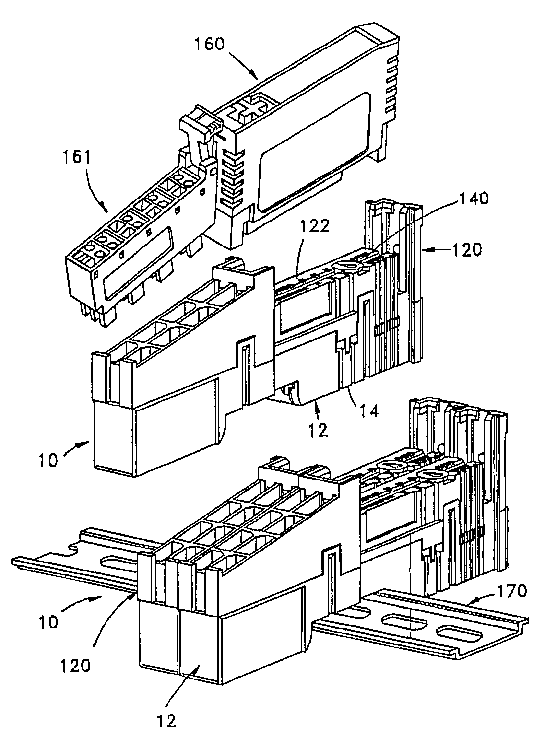
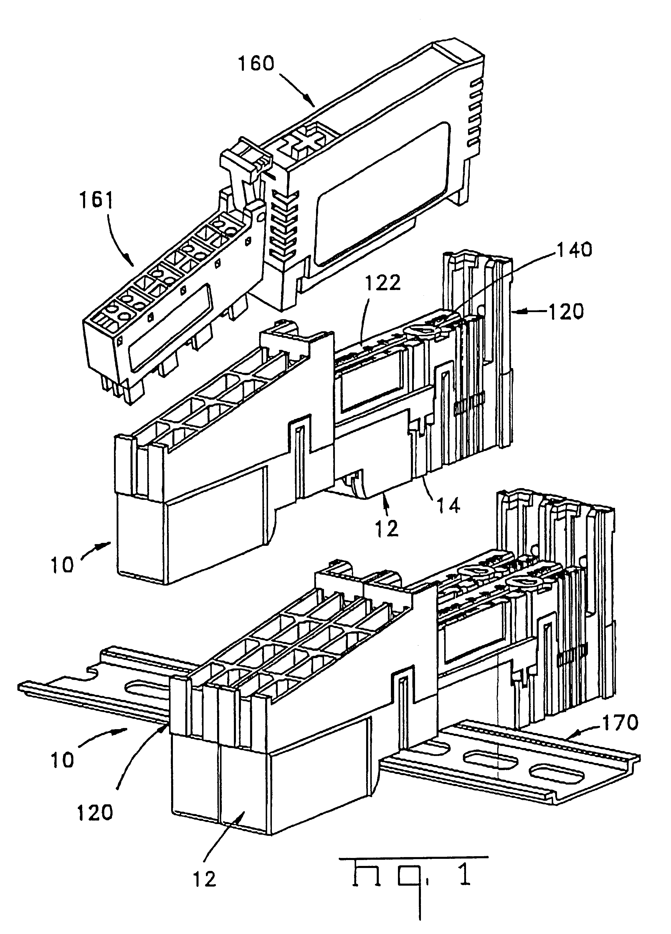
In FIG. 1 two modules, each identified as a connector assembly 10 of the present invention, are shown mounted to a rail 170 of an electronic device. A third connector assembly 10 is shown exploded from the rail 170. Two complementary mating connectors 160, 161 are exploded from the third assembly 10.

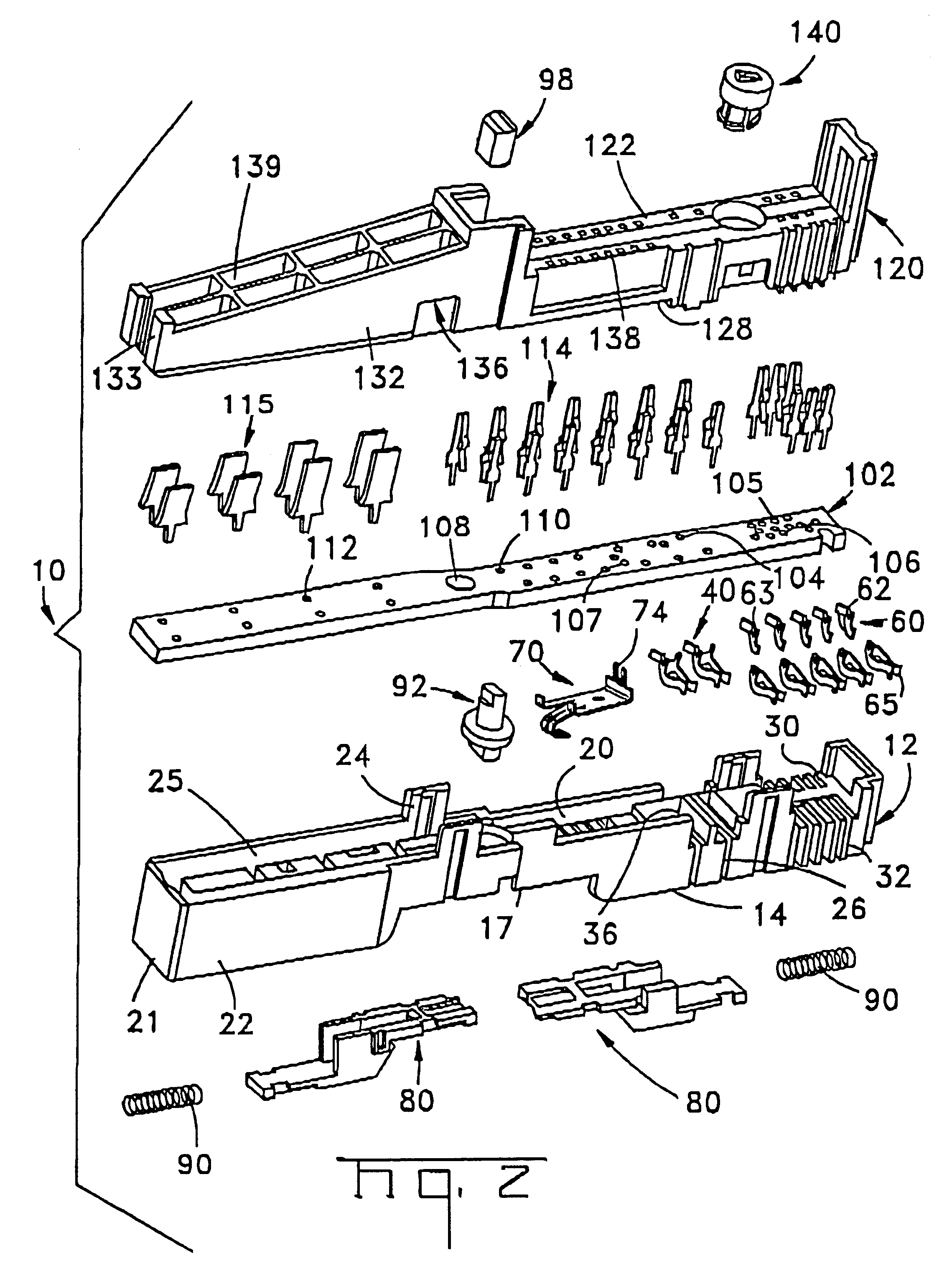
Referring now, to FIGS. 1 and 2, connector assembly 10 includes a lower housing 12 having a plurality of terminals 40, 60 and 70 disposed therein; an upper housing 120 securable to the lower housing 12 and having a plurality of terminals 114, 116 disposed therein and a circuit board 102 disposed between and within the housings 12, 120. Lower housing 12 has a rail mounting face 14 including a rail engaging recess 17, an assembly face 20, end walls 21, and side walls 22 having latch arms 24 extending upwardly therefrom and adapted to engage cooperating latch surfaces 136 on upper housing 120. End walls 21 and side walls 22 and assembly face 20 together define a circuit board receiving cavi...


PUM


Abstract

An input / output device (10) includes housings (12, 120) defining a circuit board receiving cavity (25). An input / output module 160 is removably connected to the housings (12, 120). Circuit board (102) is engaged within the circuit board receiving cavity (25) and has power and data terminals (40, 60) electrically engaged therewith. Each of the power and data terminals (40, 60) have portions extending from the circuit board (102) and are adapted for being electrically engaged with complementary portions of terminals of adjacent devices in a stacked arrangement.

Description

This invention is related to input / output devices and more particularly to electrical terminals that are used to interconnect adjacent modules in an input / output device.It is well known in the art to use a plurality of electronic input / output modules that fit together in a stacked arrangement and are electrically connected together. It is also known that the modules may be mounted to a U-shaped metal rail that supports the device and provides electrical connection to ground.U.S. Pat. No. 5,775,955 discloses one such arrangement in which each module has plug-compatible male and female connectors that are electrically engaged by sliding a loose module along a rail and into engagement with modules that are fixed to the rail. To repair or replace a selected module in the stacked arrangement, it is necessary to slide and remove all the modules to one side of the selected module from the rail before the selected module can be removed, repaired or replaced. The whole process is then repeat...

Claims


Application Information

Patent Timeline
Patent Type & Authority Patents(United States)
IPC IPC(8): H01R13/514H01R9/24H01R9/26H05K7/14
CPCH01R9/26H01R9/2658H01R13/514H05K7/1441H05K7/1468H05K7/1478Y10S439/928
Inventor LOSTOSKI, DOUGLAS A.WEHRLE, DAVID S.BALL, GAIL R.
Owner ROCKWELL AUTOMATION TECH
Why Eureka
Try Eureka