
Lint roller assembly

a technology of lint rollers and assemblies, which is applied in the direction of artistic surface treatment, household cleaners, coatings, etc., can solve the problems of affecting the free rotation of the lint roller

Inactive Publication Date: 2002-08-06
BUTLER HOME PRODUCTS LLC
View PDF17 Cites 33 Cited by
  • Summary
  • Abstract
  • Description
  • Claims
  • Application Information

AI Technical Summary

Benefits of technology

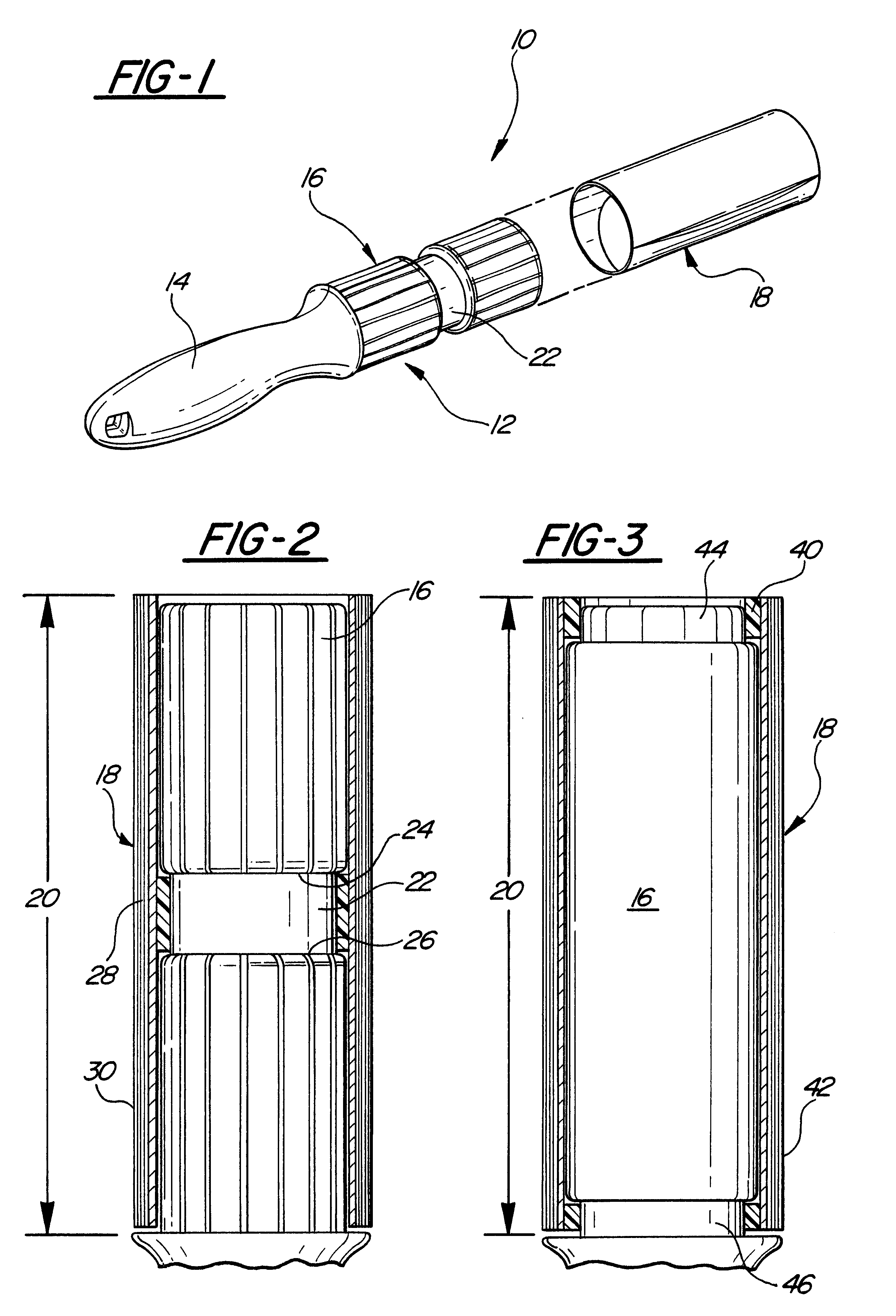
The lint roller support section is substantially cylindrical in shape and includes a radially recessed and circumferentially extending channel formed between its ends. This channel, furthermore, has a longitudinal length less than the longitudinal length of the lint roller support section.
The lint roller assembly further comprises a lint roller having a tubular cylindrical core and an adhesive sheet roll wound about the core. This core has a longitudinal length and inside diameter dimensioned to fit into the lint roller support section channel. Furthermore, the longitudinal length of the adhesive roll is substantially the same as the longitudinal length of a lint roller support section and, as such, is substantially less than the longitudinal length of the adhesive roll.
The inside diameter of the core is substantially the same or slightly less than the outside diameter of the lint roller suppor...

Problems solved by technology

One disadvantage is that, since the fingers are positioned along the outer end of the core, as the lint roller rotates on the lint roller support section, the fingers abrade the axial end of the core and create cardboard dust.
A still further disadvantage of the previously known lint rollers is that, since the inner cardboard core extends along the entire length of the lint roller support, a relatively large area of contact between the core and the lint roller support section is created during the use of the lint roller.
This, in turn, inhibits the desired free rotation of the lint roller relative to the lint roller support section.
A still further disadvantage of these previously known lint roller assemblies is that, since the axial length of the core is the same as the axial length of the adhesive roll, the core constitutes a significant portion of the overall cost of the lint roller.
Furthermore, after the adhesive roll has been depleted, the core is simply discarded which can result in excessive waste.

Method used


Image

  • Lint roller assembly
  • Lint roller assembly

Examples


Embodiment Construction

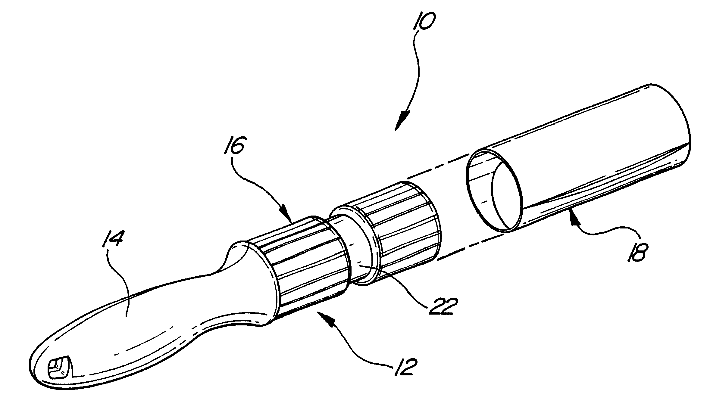
With reference first to FIG. 1, an exploded view of the preferred embodiment of the lint roller assembly 10 of the present invention is there shown and comprises an elongated housing 12 having both a handle 14 and a lint roller support section 16. A tubular and cylindrical lint roller 18 is slidably received over the lint roller support section 16 and retained to the lint roller support section 16 in a manner subsequently described in greater detail.

Referring now to FIGS. 1 and 2, the lint roller support section 16 is generally cylindrical in shape and has a predetermined axial or longitudinal length 20. A radially recessed and circumferentially extending channel 22 is formed at a midpoint of the lint roller support section 16. The channel 22 includes two sides 24 and 26 and the longitudinal length of the channel 22 between its sides 24 and 26 is substantially less than the longitudinal length 20 of the lint roller support section 16.

With reference now particularly to FIG. 2, the li...


PUM


Abstract

A lint roller assembly is disclosed having an elongated housing with a handle and a lint roller support section longitudinally adjacent the handle. The lint roller support section is substantially cylindrical in shape and has a radially recessed and circumferentially extending channel formed between its ends. This channel has a longitudinal length less than the longitudinal length of the lint roller support section. The lint roller assembly further includes a lint roller having a tubular cylindrical core and an adhesive sheet roll wound about the core. The core has a longitudinal length and inside diameter dimensioned to fit into the channel such that the lint roller is retained to the lint roller support section. The longitudinal length of the core, furthermore, is less than the longitudinal length of the adhesive roll.

Description

I. Field of the InventionThe present invention relates generally to lint roller assemblies.II. Description of the Prior ArtThere are many previously known lint roller assemblies. These previously known lint roller assemblies typically comprise a handle secured to a cylindrical lint roller support. A tubular cylindrical adhesive lint roller is then removably mounted to the support such that the adhesive roller is rotatable relative to the handle. In use, the adhesive lint roller is rolled along the user's clothes or other area to remove lint, hair and other debris.Typically, the lint roller comprises a cylindrical tubular cardboard core with the adhesive roll wound about the core. Furthermore, the axial length of the core is substantially the same as the axial length of the adhesive roll.In order to retain the lint roller to the lint roller support for these previously known assemblies, a radially extending abutment surface is positioned at the junction of the handle with the lint ro...

Claims


Application Information

Patent Timeline
IPC IPC(8): A47L25/00
CPCA47L25/005
Inventor MCKAY, JR., NICHOLAS D.
Owner BUTLER HOME PRODUCTS LLC
Learn More