Vibratory separator with material heater

a technology of vibrating separator and material heater, which is applied in the direction of solid separation, screening, chemistry apparatus and processes, etc., can solve the problems of insufficient tension on the screen, the tension bolt is bent, and the nut cannot be effectively adjusted, so as to reduce or eliminate the binding of the grip plate

Inactive Publication Date: 2002-08-27
VARCO I P INC
View PDF52 Cites 61 Cited by
  • Summary
  • Abstract
  • Description
  • Claims
  • Application Information

AI Technical Summary

Benefits of technology

The swivel permits the links to align with the bolt to reduce or eliminate binding of the grip plate with the side mount of a vibratory screen apparatus.

Problems solved by technology

Often, the nut can only be effectively adjusted when the structure is in an unlocked position.
With some prior art devices sliding surfaces must be lubricated regularly, otherwise the surfaces gall making high torque necessary, which in turn requires a high wrench load which can result in a bent tension bolt.
Certain prior art devices can result in insufficient tension on a screen when their springs collapse (take a set) reducing the total tension load produced by the spring.

Method used


Image

  • Vibratory separator with material heater
  • Vibratory separator with material heater
  • Vibratory separator with material heater

Examples


Embodiment Construction

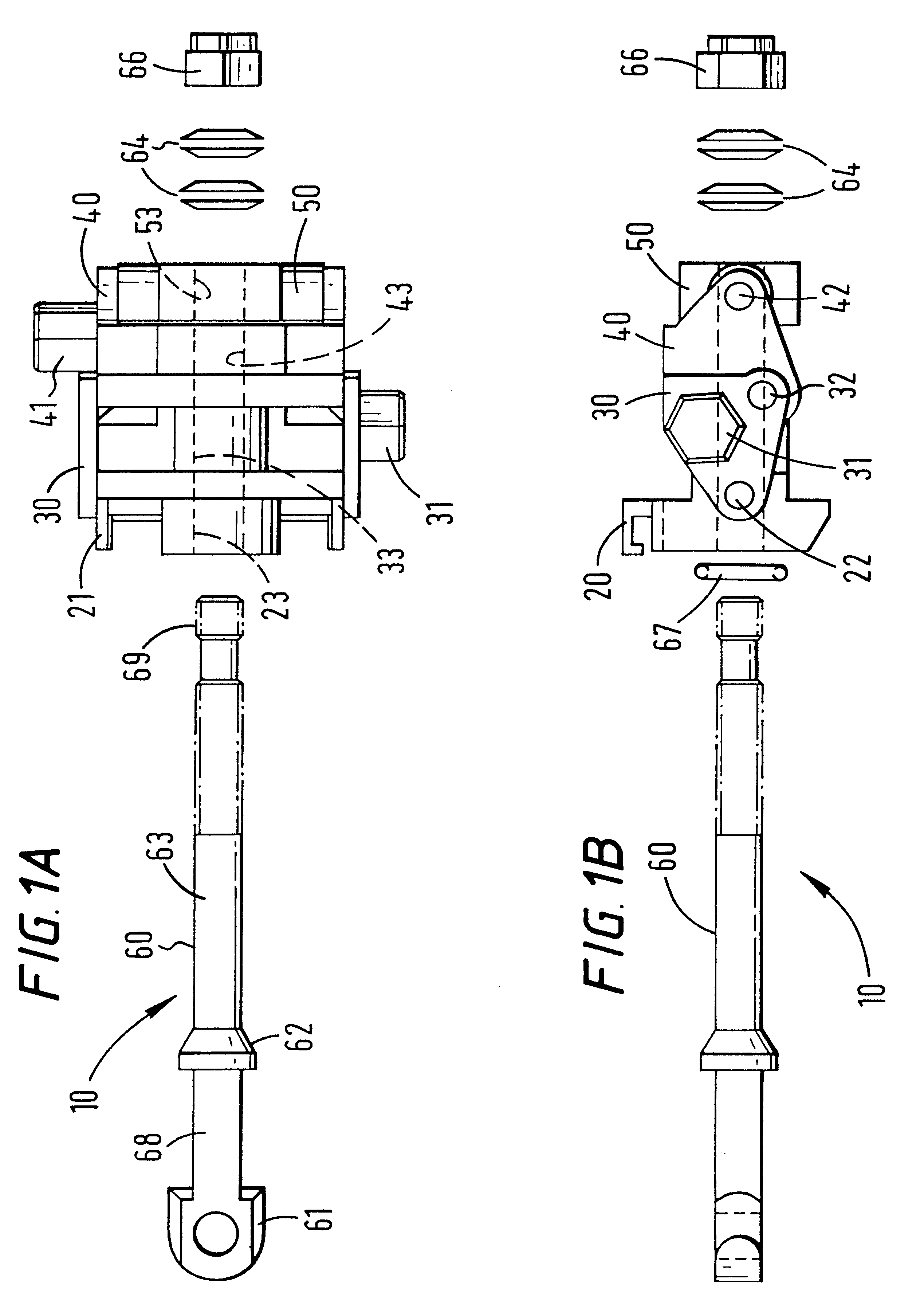
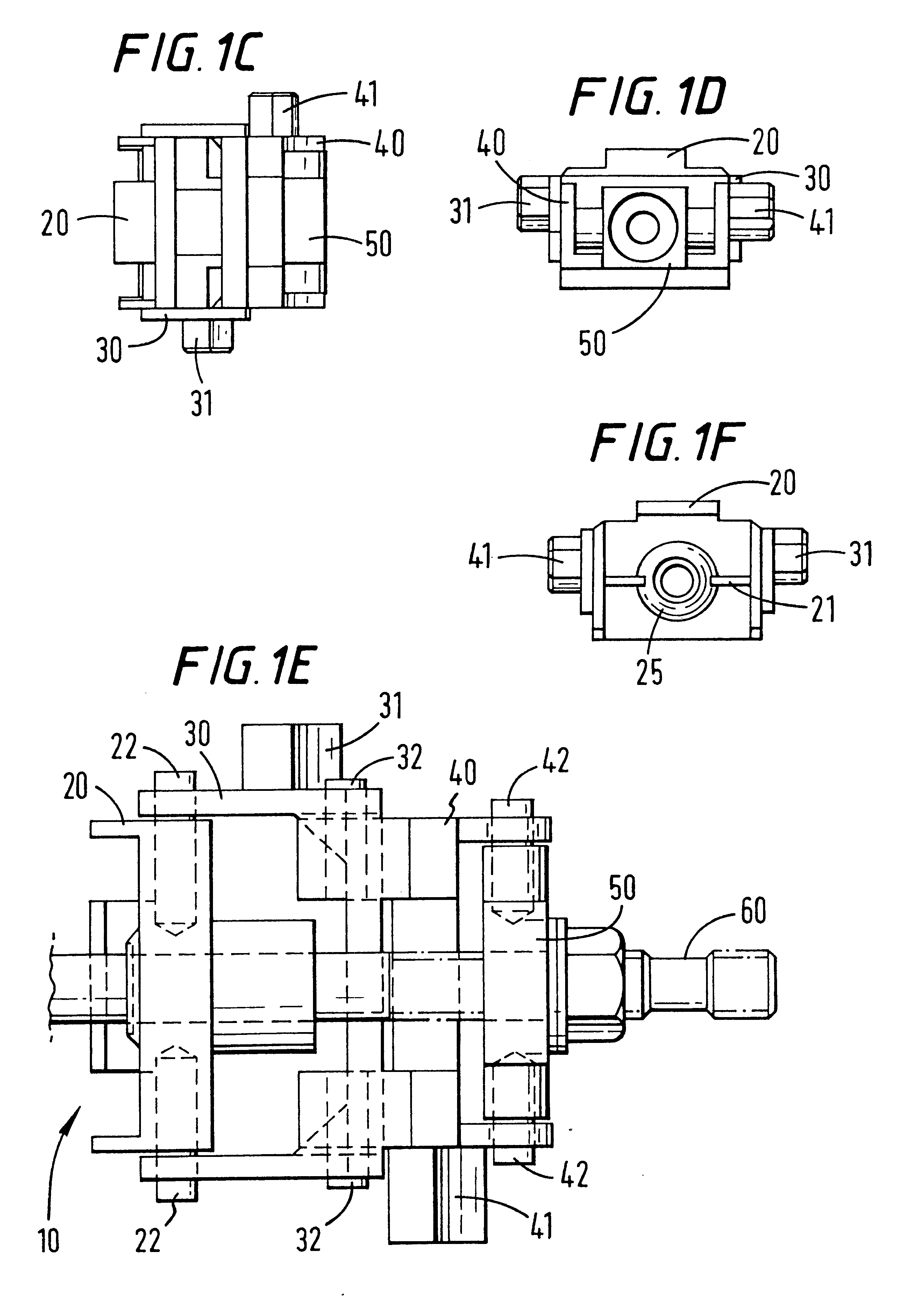
Referring now to FIGS. 1A-1F a device 10 according to the present invention has a bolt 60 that extends through a plate 20, a first link 30, a second link 40 and a swivel 50. A nut 66 threadedly mates with threads 69 to releasably hold the bolt 60 in position.

The bolt 60 has a shaft portion 63 that extends movably through a channel 23 in the plate 20 (see FIGS. 6A-6D). On a front side of the plate 20 a raised portion 25 facilitates holding a head of the bolt 60 in a position to more easily engage a tension rail. An O-ring or other sealing member 67 (see FIG. 1B) is, optionally, disposed in a recess 23 within the raised portion 25 and seals against portion 62 of the bolt 60.

An optional cylinder 29 projects from the rear side of the plate 20 and the channel 23 extends all the way through the plate 20 to the rear end of the cylinder 29. As will be discussed below, the rear side of the cylinder 29 provides a stop against which movement of the swivel 50 is stopped.

Arms 28 and arm 24 relea...


PUM


Abstract

A vibratory separator apparatus for separating components from a fluid material stream fed to the vibratory separator apparatus, the vibratory separator apparatus, in certain aspects, having separator apparatus for separating components of the fluid material stream, and heating apparatus for heating the fluid material stream. A screening system with a screen mounting basket, at least one screen mounted on the basket, and heating apparatus for heating the at least one screen. Methods are disclosed for using such apparatuses and systems

Description

1. Field of the InventionThis invention is directed to vibratory separators and to such separators with heating appratus for heating material to be treated.2. Description of Related ArtThe prior art discloses a variety of devices and apparatuses for securing a screen to a vibratory screening apparatus. Many of the prior art systems employ a simple bolt, nut, and plate combination, with or without shock absorbing material. Tightening and loosening of the nut provides tension adjustment. Exemplary prior art patents include, but are not limited to, U.S. Pat. Nos. 4,303,509; 5,332,101; and 5,392,925.U.S. Pat. No. 5,332,101 discloses a screen tensioning structure that includes body members with a cam arrangement whose movement creates a pulling effect when cam followers slide up camtracks. Certain commercially available embodiments require a special wrench to turn a movable adjustment nut. Often, the nut can only be effectively adjusted when the structure is in an unlocked position. With...

Claims


Application Information

Patent Timeline
Patent Type & Authority Patents(United States)
IPC IPC(8): B07B1/48B07B1/56B07B1/46
CPCB07B1/48B07B1/56
Inventor SEYFFERT, KENNETH WAYNE
Owner VARCO I P INC
Why Eureka
Try Eureka