Printing head and ink jet recording apparatus using the same

a recording apparatus and printing head technology, applied in printing, washing apparatus, textiles and paper, etc., can solve the problems of reducing printing quality, sacrificing work accuracy, and lowering the density of the nozzl

Inactive Publication Date: 2002-09-10
SEIKO EPSON CORP
View PDF7 Cites 126 Cited by
  • Summary
  • Abstract
  • Description
  • Claims
  • Application Information

AI Technical Summary

Problems solved by technology

However, the following problems are pointed out when the material of the head is changed and replaced by another material which is not dissoluble in the ink.
First, the change of the material of the ink jet head causes sacrifices in accuracy of working and in easiness of fine working.
As a result, lowering of nozzle density and hence lowering of printing quality may be caused.
The diaphragm which is a bottom plate of the; pressure chamber is easily affected by corrosion because the diaphragm is extremely thin.

Method used


Image

  • Printing head and ink jet recording apparatus using the same
  • Printing head and ink jet recording apparatus using the same
  • Printing head and ink jet recording apparatus using the same

Examples


embodiment 1

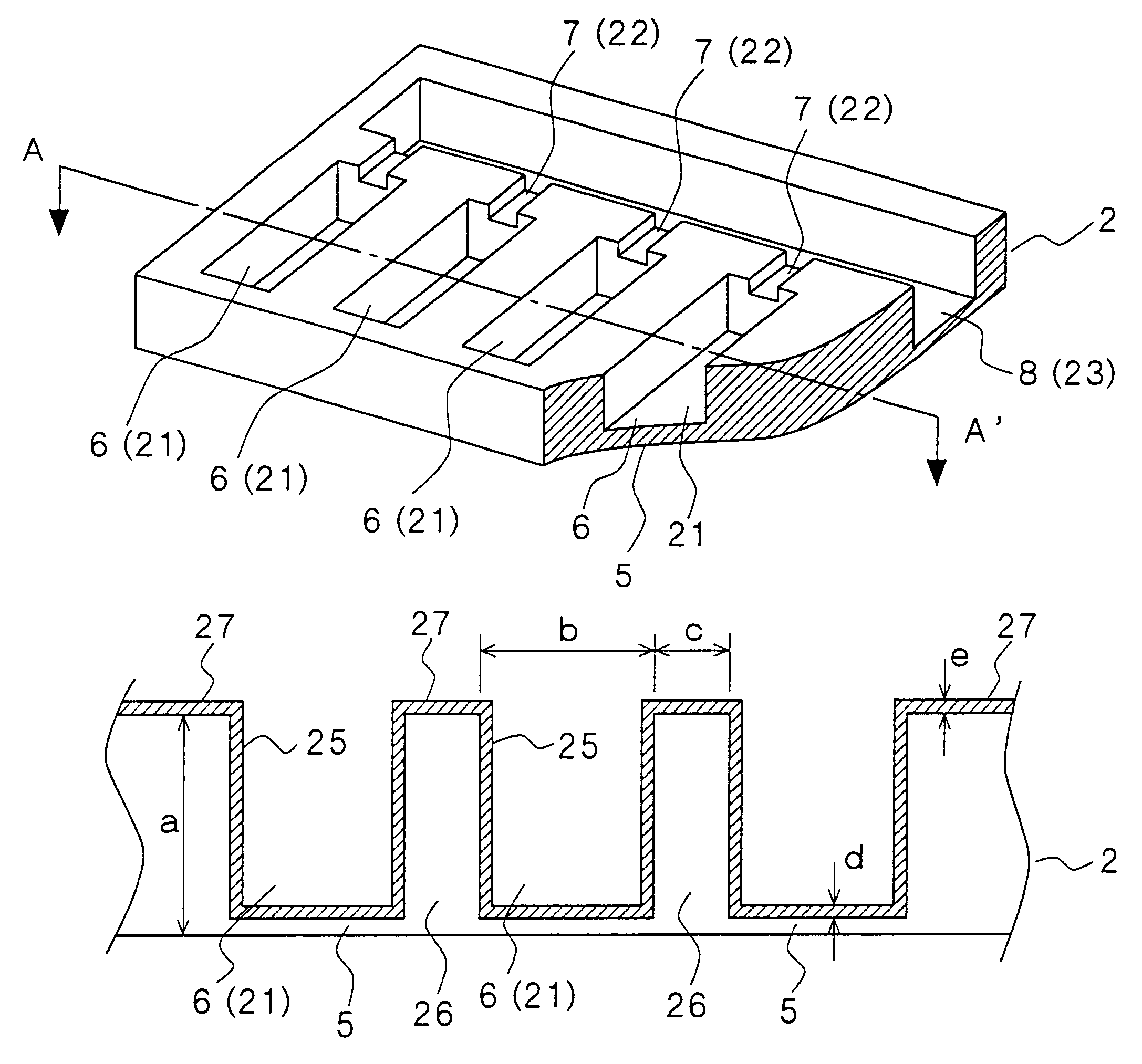
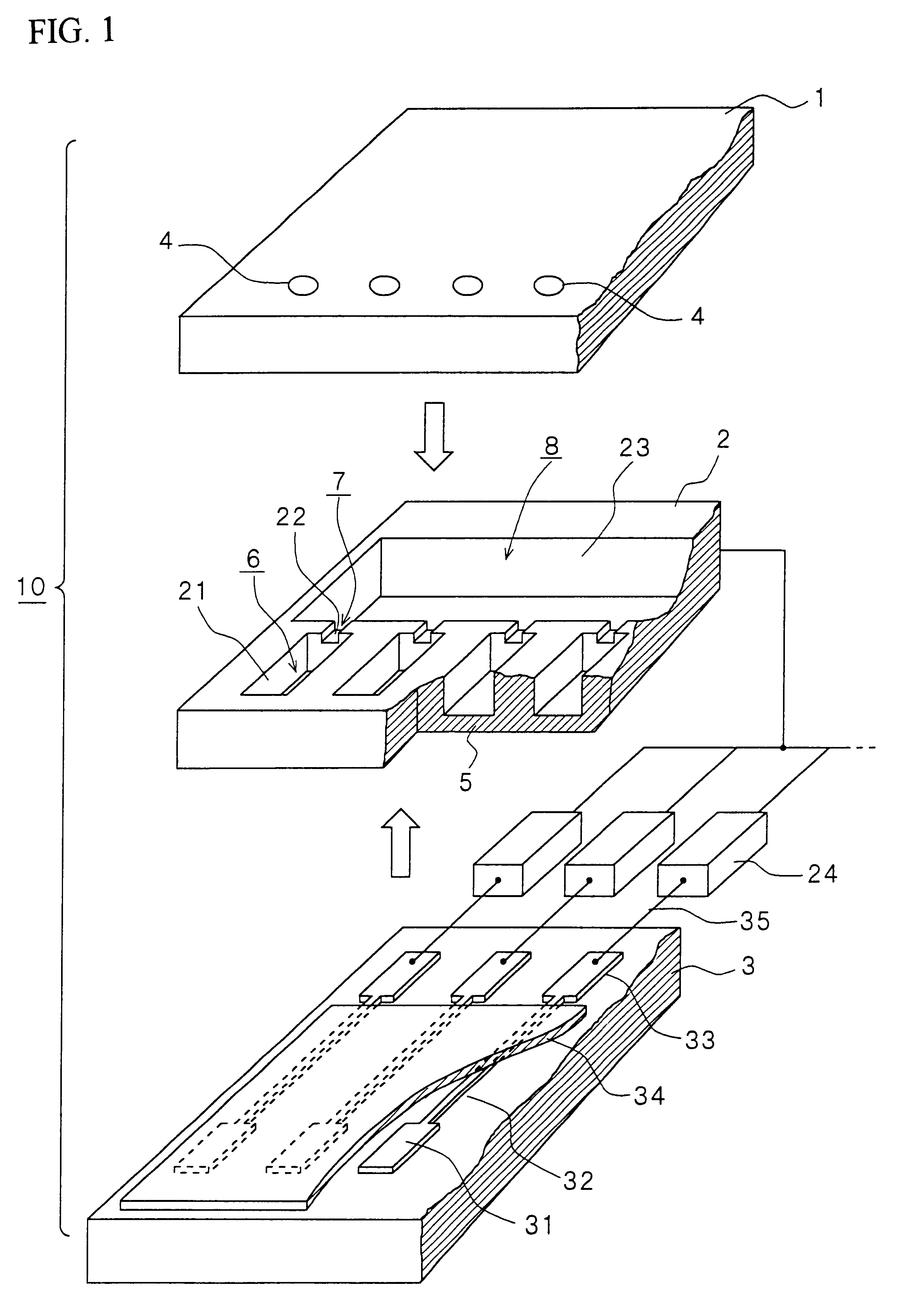
A driving method of an electrostatic system is adopted in an ink jet head 10 according to this embodiment. The ink jet head has a lamination structure in which three substrates 1, 2 and 3 having a structure which will be described in detail later are laminated one on another and bonded with each other, as shown in FIGS. 1 and 2. The upper substrate 1 made of, for example, silicon, glass or plastic is provided with a plurality of nozzle holes 4 (the pitch is about 70 .mu.m, and the diameter is about 25 .mu.m) so as to form a nozzle plate. The intermediate substrate 2 is constituted by, for example, a silicon single-crystal substrate. The intermediate substrate 2 has recess portions 21 communicating with the nozzle holes 4 and constituting pressure chambers 6 with their bottom walls acting as diaphragms 5; narrow grooves 22 provided at the rear of the recess portions 21 so as to constitute orifices 7 acting as ink inlets; and a recess portion 23 constituting a common reservoir 8 for f...

embodiment 2

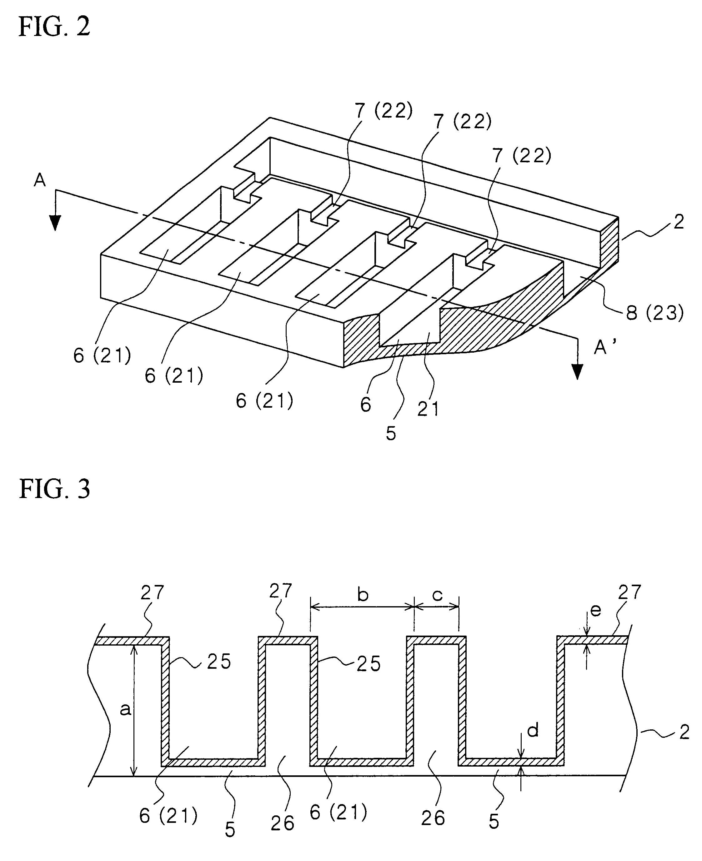
In this embodiment, titanium nitride (hereinafter referred to as "TiN") is laminated all over the surface of an ink flow path (recess portions 21 to 23 constituting pressure chambers 6, orifices 7 and a reservoir 8) of an intermediate substrate 2 having the same shape as that in Embodiment 1, by any one of a sputtering method, a vacuum deposition method, an ion plating method, and a CVD method so as to form an ink-resistant thin film. The thin film has the same sectional shape as that in the above-mentioned Embodiment 1, as shown in FIG. 3.

Although TiN is laminated so that the film thickness thereof is 1,000 .ANG. on the surface of the diaphragm 5 (the size d in FIG. 3), the TiN film thickness on each surface 27 (the size e in FIG. 3) at that time varies in accordance with the laminating method used therefor, as shown in the following Table 2.

embodiment 3

In this embodiment, titanium oxide (hereinafter referred to as "TiO.sub.2 ") is laminated all over the surface of an ink flow path (recess portions 21 to 23 constituting pressure chambers 6, orifices 7 and a reservoir 8) of an intermediate substrate 2 having the same shape as that in Embodiment 1, by any of sputtering, vacuum deposition, ion plating, and CVD, so as to form an ink-resistant thin film. The thin film has a sectional shape as shown in FIG. 3, in the same manner as that in the above-mentioned Embodiment 1.

Although TiO.sub.2 is laminated so that the film thickness thereof is 1,000 .ANG. on the surface of the diaphragm 5 (the size d in FIG. 3), the TiO.sub.2 film thickness on the surfaces 27 (the size e in: FIG. 3) at that time varies in accordance with a laminating method used therefor, as shown in the following Table 3.


PUM


Abstract

An ink jet head which is -prevented from corrosion by ink, and an ink jet recording apparatus using the same. An ink-resistant thin film (25) made of Ti, a Ti compound, or Al2O3 is formed on the surface of recess portions (21 to 23) of a substrate in which a reservoir (8) for reserving ink, orifices (7) and pressure chambers (6) are formed. Since this ink-resistant thin film (25) is formed, corrosion can be restrained without reducing printing quality, without necessity to change the component/composition of the ink and the material of the head, and with little change of its manufacturing process, even if there is a fear that the head material may be corroded by the ink.

Description

The present invention relates to a printing head ejecting ink drops to print (hereinafter referred to as "ink Jet head"), and an ink jet recording apparatus using the same.BACKGROUND TECHNIQUERecently ink jet recording apparatuses have come into wide use with the developments of printing in high picture quality and in colors. Of those developments, first, about the development of printing in high picture quality, the improvement of nozzle density in an ink jet head played a very large part. As the result of various investigation and development therefor, silicon, glass, photosensitive dry film, ceramics, etc. as well as metal and plastic used conventionally have come into use for an ink jet head in view of easiness in fine working, accuracy in working, process etc. In addition, to realize printing in high picture quality and in colors, investigation and development have been performed also upon ink. In order to optimize permeability or coloring properties of ink in the case where in...

Claims


Application Information

Patent Timeline
Patent Type & Authority Patents(United States)
IPC IPC(8): B41J2/14B41J2/16
CPCB41J2/14201B41J2/14314B41J2/1607B41J2/1623B41J2/1642B41J2/1643B41J2/1646B41J2202/03
Inventor CHINO, YUJIARAKAWA, KATSUJI
Owner SEIKO EPSON CORP
Why Eureka
Try Eureka