Structure of a vacuum display device

a display device and vacuum technology, applied in the manufacture of electrode systems, tubes with screens, electric discharge tubes/lamps, etc., can solve the problems of damage to the electron gun, limited resolution of the display device, and the way in which the wires for the electrodes exit the glass housing

Inactive Publication Date: 2002-09-10
DELTA ELECTRONICS INC
View PDF0 Cites 1 Cited by
  • Summary
  • Abstract
  • Description
  • Claims
  • Application Information

AI Technical Summary

Problems solved by technology

A high degree of vacuum state must be maintained in the cathode ray tube since air molecules would retard the efficiency of the bombardment from the electron gun and the free ions generated by the bombardment would damage the electron gun.
For this reason, there is a 5.6 mm (2.8 mm.times.2) of edge space for each device that must be excluded from the image display; therefore, the resolution of the display device is limited.
Another limitation is the way in which wires for the electrodes exit the glass housing.
In this case, the process of drilling holes through the glass is rather difficult and complicated.
This makes the fabrication difficult and expensive.
Additionally, the number of X and Y drives is limited; if not, the base plate with a large number of holes would cause difficulty during element printing on the base plate.

Method used


Image

  • Structure of a vacuum display device
  • Structure of a vacuum display device
  • Structure of a vacuum display device

Examples


Embodiment Construction

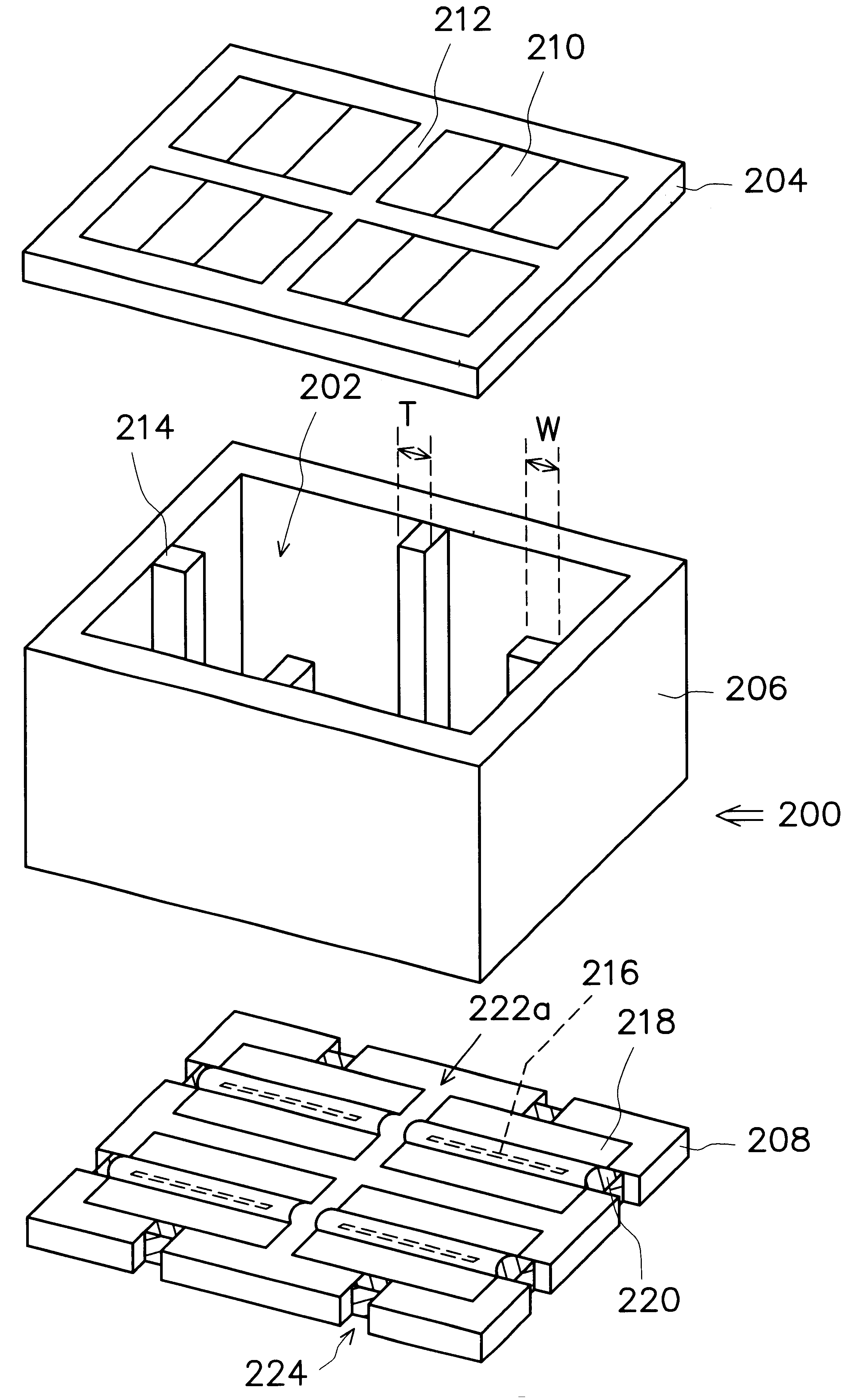
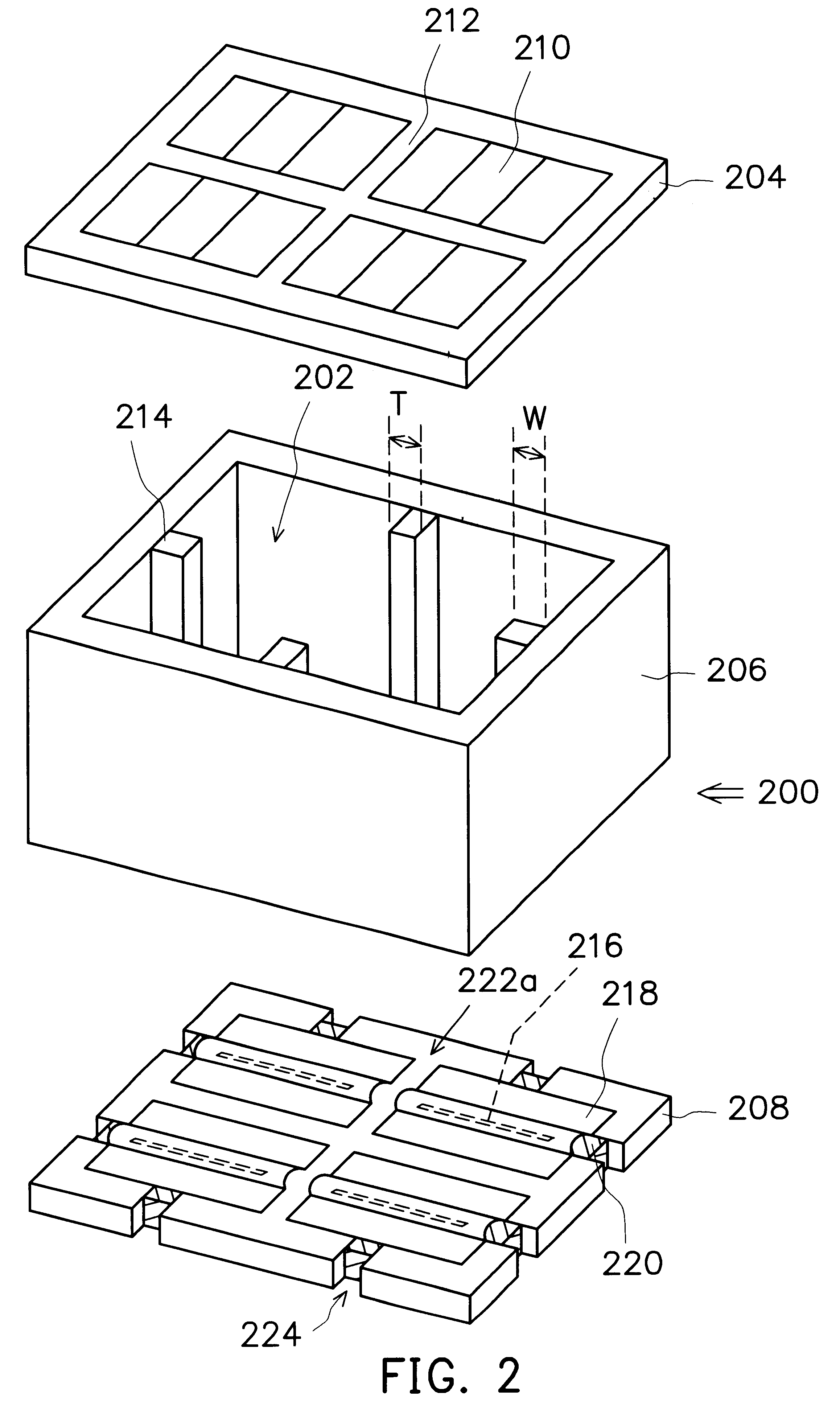
FIG. 2 illustrates an exploded view of a structure of a vacuum display device according to the preferred embodiment of the present invention. Referring to FIG. 2, the vacuum display device 200 is constructed in a vacuum chamber 202. The vacuum chamber 202 is formed by a surface plate 204, a spacer plate 206, and a base plate 208, which are made of material such as glass. The sealing material (not shown) for sealing the connections between them includes a polymer sealing material (e.g. epoxy), a ceramic material, etc. The surface plate 204 is divided into a display matrix 210 having its inner surface coated with a fluorescent powder, and a black matrix used for the purpose of enhancing contrast, wherein the display matrix, for example, consists of three different display fluorescent powder matrix blocks: red, green, and blue.

Fins 214 are set up on the spacer plate 206 at locations corresponding to that of the black matrices 212 to reinforce the force-sustaining structure of the vacuu...


PUM


Abstract

A structure of a vacuum display device is mainly constructed in a vacuum chamber, which is formed by the enclosure of a surface plate, a base plate, and a spacer plate. The surface plate includes a display matrix and a black matrix, the base plate includes an inner surface and an outer surface, while the spacer plate possesses a plurality of recesses in its edges. The required electrode lead wires are disposed on the inner surface of the base plate and are extended out through the recesses. A plurality of fins are disposed on the spacer plates to support the surface plate, the base plate, and the spacer plate, and are located at the black matrices. Additionally, sealing material is used to seal the connections between the surface plate, the base plate, and the spacer plate, and is also used to fill the gaps in the recesses.

Description

This application claims the priority benefit of Taiwan application serial no. 88117224, filed Oct. 6, 1999.1. Field of the InventionThis invention relates to a structure of a vacuum display device, and more particularly to a reinforced structure to strengthen the structure of a high voltage vacuum fluorescent display (HVVFD), and a reinforced structure to strengthen the structure of a high voltage vacuum fluorescent electrode.2. Description of Related ArtThe vacuum device has been a very popular product in the market for a long time. Its range of application is very wide, for example, display devices, stereos, etc. Display devices with high luminosity have been widely used in many situations for forwarding information, for instance, a scoreboard in a stadium, an electronic digital display in a public area, a bulletin board on highway for showing directions and road conditions, etc. The display screen used in a large electronic digital display is a display technology consisting of ma...

Claims


Application Information

Patent Timeline
Patent Type & Authority Patents(United States)
IPC IPC(8): H01J29/86H01J9/26H01J5/02H01J29/90H01J31/12
CPCH01J9/261H01J29/862H01J2329/00
Inventor CHEN, LAI-CHENGTSAI, CHUN-HUILIN, SHIH-HSIENJEAN, RUEY-FENG
Owner DELTA ELECTRONICS INC
Why Eureka
Try Eureka