Tube for conveying a liquid

a technology for conveying tubes and liquids, which is applied in the direction of flexible pipes, heat exchange apparatus, heat exhanger conduits, etc., can solve the problems of more difficult kinks in tubes, and achieve the effect of more rigidity in tubes

Inactive Publication Date: 2002-09-24
SMITH DONALD
View PDF16 Cites 26 Cited by
  • Summary
  • Abstract
  • Description
  • Claims
  • Application Information

AI Technical Summary

Benefits of technology

The side walls of the tube are thicker than the top and bottom walls so as to give more rigidity to the tube, and as a result the tube will not kink and fold back on itself.
The thickening of the side walls of the tube can be realized by having outriggers on the tube. The outriggers stiffen the tube and make it more difficult for the tube to kink.
As the tube can be extruded with the use of these elastomers, the cost to manufacture the tube is a relatively low cost.
It takes less space to stock and store the tube in a warehouse or retail store as the tube can readily be wound onto a reel or formed into a coil.
I have found that the tube drags more easily around obstructions than the standard garden hose which in a lateral view is circular.

Problems solved by technology

The outriggers stiffen the tube and make it more difficult for the tube to kink.

Method used


Image

  • Tube for conveying a liquid
  • Tube for conveying a liquid
  • Tube for conveying a liquid

Examples


Embodiment Construction

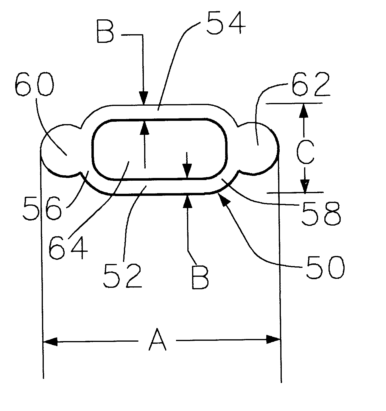
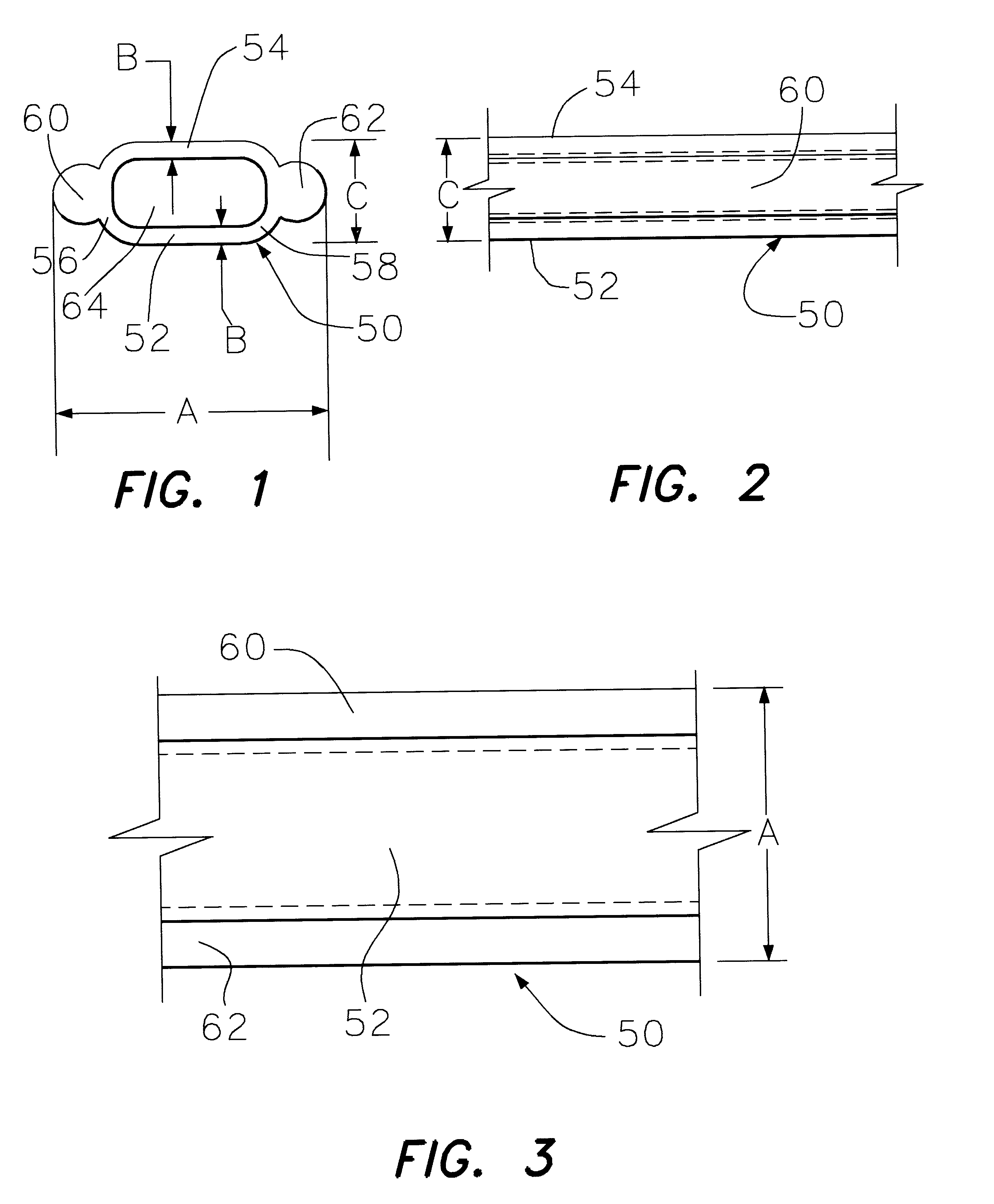
With reference to FIGS. 1-4 it is seen that there is a tube 50 having a bottom side 52 and a top side 54.

There is a first curved end 56 connecting 52 and 54.

There is a second curved end 58 connecting 52 and 54.

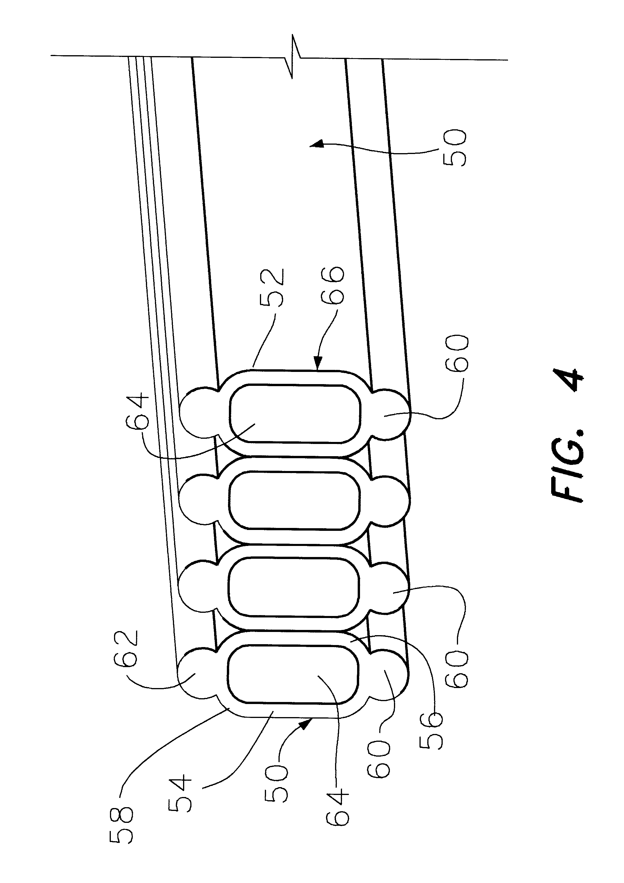
On the outer surface of the first curved end 56 there is a first outrigger 60.

On the outer end of the second curved end 58 there is a second outrigger 62.

The top side, bottom side, first curved end, and the second curved end have an inside surface and define a central passageway 64.

In FIG. 4 there is illustrated a coil 66 of the tube 50 in a coiled relationship with the cross-section of the tube 50 illustrated.

The outside dimension A from the outside of the first outrigger 60 and the outside of the second outrigger 62 may be about 1.10 inches.

The thickness of the bottom wall, see dimension B, and the top wall may be about 0.075 inches.

The diameter of the outrigger 60 and the outrigger 62 may be about 0.25 inches.

The thickness of the tube 50, see dimension C, can be about 0.40 ...


PUM

PropertyMeasurementUnit
diameteraaaaaaaaaa
lengthaaaaaaaaaa
thicknessaaaaaaaaaa

Abstract

A round circular hose has a tendency to kink when extended. Also, a round circular hose can be difficult to form into a coil. With this background I have developed a hose with rigid sides to prevent kinking and for ease for forming into a coil provided with thicker wall sections.

Description

(C) STATEMENT AS TO RIGHTS TO INVENTIONS MADE UNDERFEDERALLY SPONSORED RESEARCH AND DEVELOPMENT (if any)This invention was developed with private funds and there were no federally assisted funds.(D) REFERENCE TO A "MICROFICHE APPENDIX"This section is not applicable to this subject matter.(E) BACKGROUND OF THE INVENTION1. Field of the InventionThe subject is a tube for conveying a liquid.An example is a hose for conveying water for a lawn, garden, or to extinguish a fire, or to wash an automotive vehicle, and the like.2. Description of the Related Art Including Information Disclosed Under 37 CFR 1.97 and 37 CFR 1.98A patent search was made on the Internet at website http: / / www.uspto.gov. A conflicting invention was not found in the patent search.Garden hoses have been used for a number of years.There are different grades in garden hoses. Garden hoses are generally made from a plastic and there may be imbedded a cloth mesh in the garden hose to add strength. A garden hose, in cross-se...

Claims


Application Information

Patent Timeline
Patent Type & Authority Patents(United States)
IPC IPC(8): F16L11/22F16L11/00B29C47/00B29C48/00B29C48/09B29C48/11B29C48/12
CPCB29C47/0023B29C47/0028B29C47/003F16L11/22B29C47/00Y10S138/11Y10S138/08B29C48/00B29C48/09B29C48/11B29C48/12
Inventor SMITH, DONALD
Owner SMITH DONALD
Why Eureka
Try Eureka