Animal confinement device

a technology for confined animals and devices, which is applied in the field of animal confinement devices, can solve the problems of serious injury to persons or other animals in the vicinity of the hind quarters of the animal, and the device does not serve to restrain the hind legs of the animal, and can discourage the animal from moving

Inactive Publication Date: 2002-10-29
TAYLOR WILLIAM
View PDF5 Cites 16 Cited by
  • Summary
  • Abstract
  • Description
  • Claims
  • Application Information

AI Technical Summary

Problems solved by technology

However, these devices do not serve to restrain the hind legs of the animals.
Consequently any person or other animal in the vicinity of the hind quarters of the animal can be seriously hurt if the animal

Method used


Image

  • Animal confinement device
  • Animal confinement device
  • Animal confinement device

Examples


Embodiment Construction

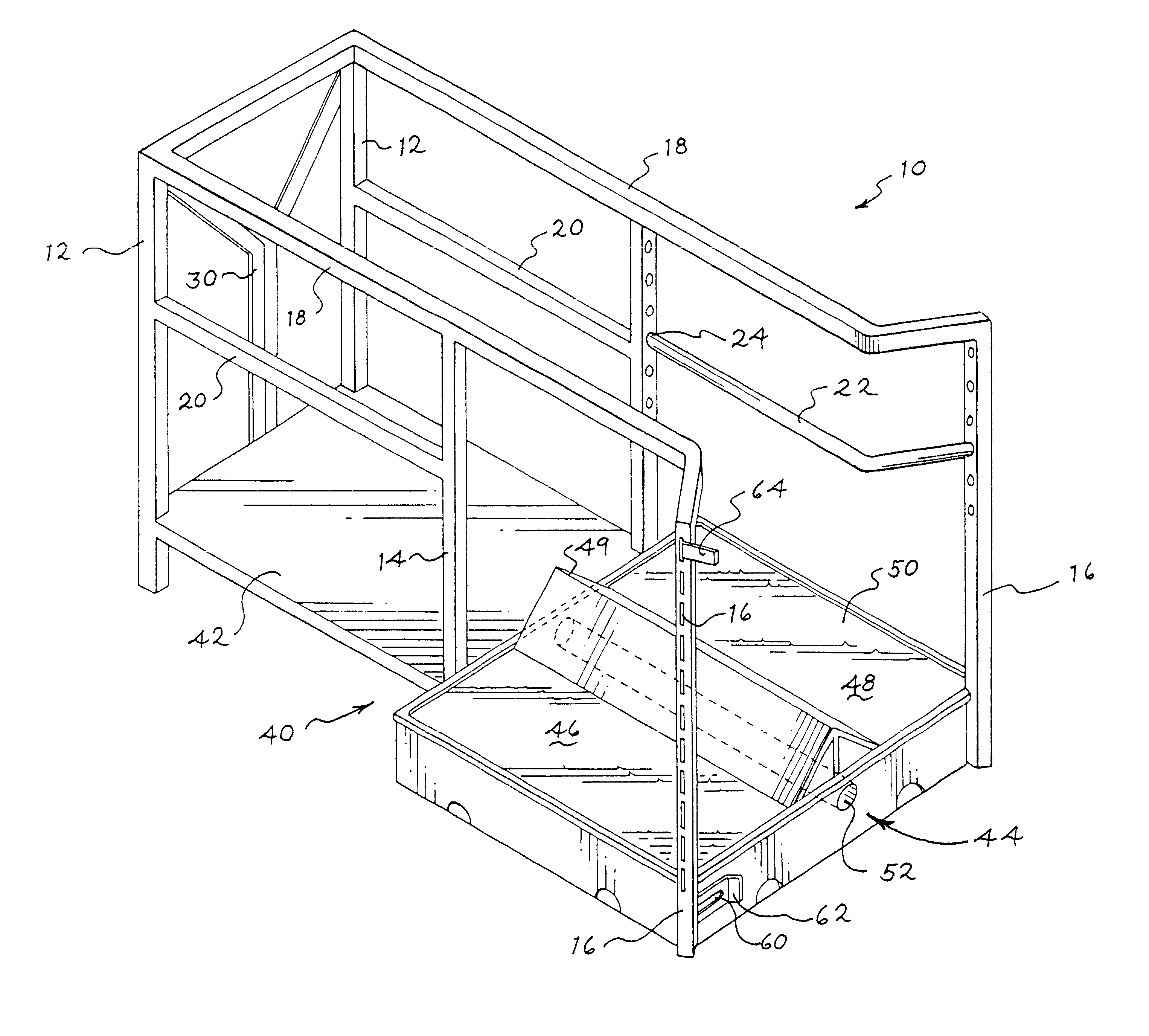
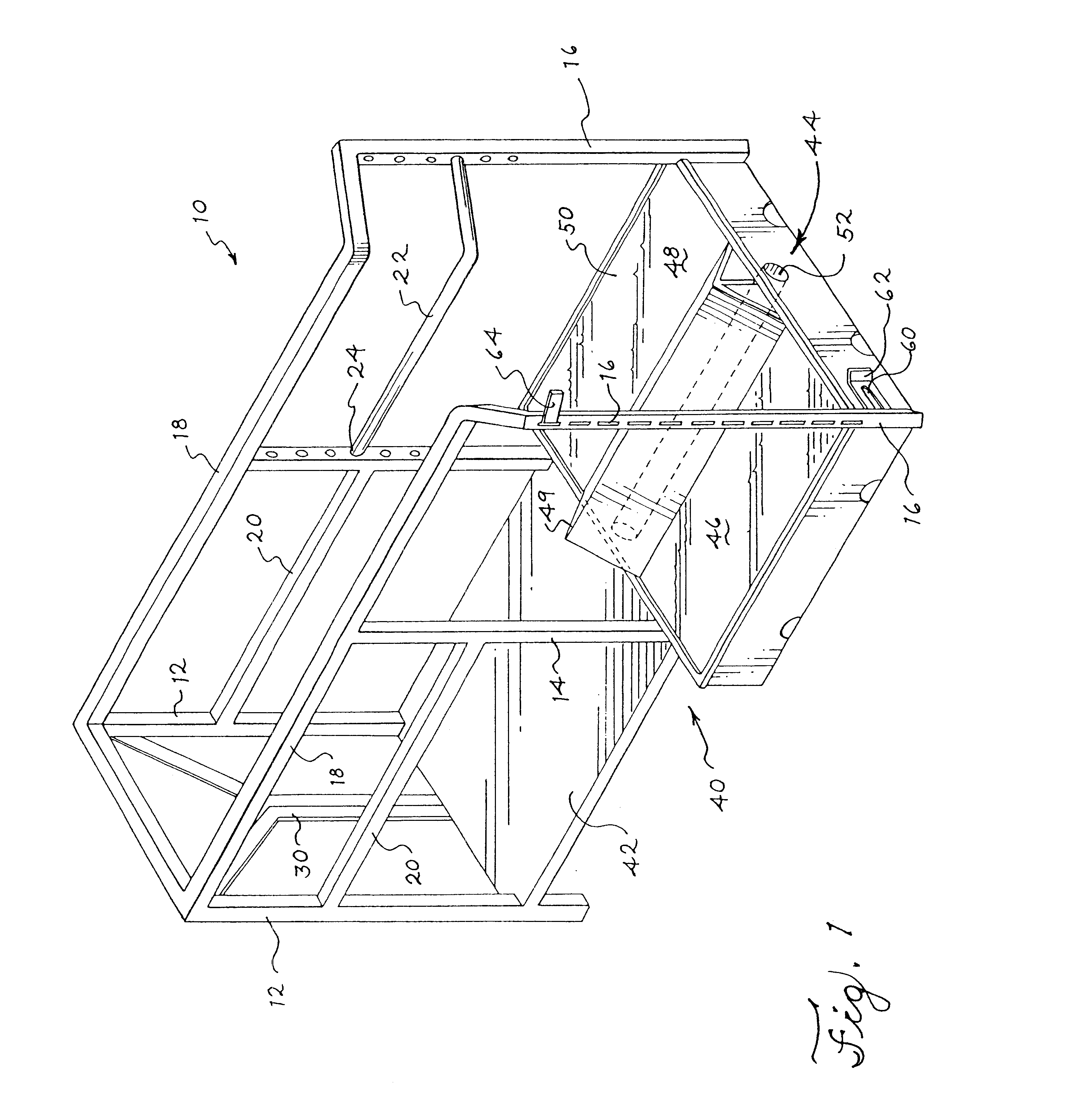
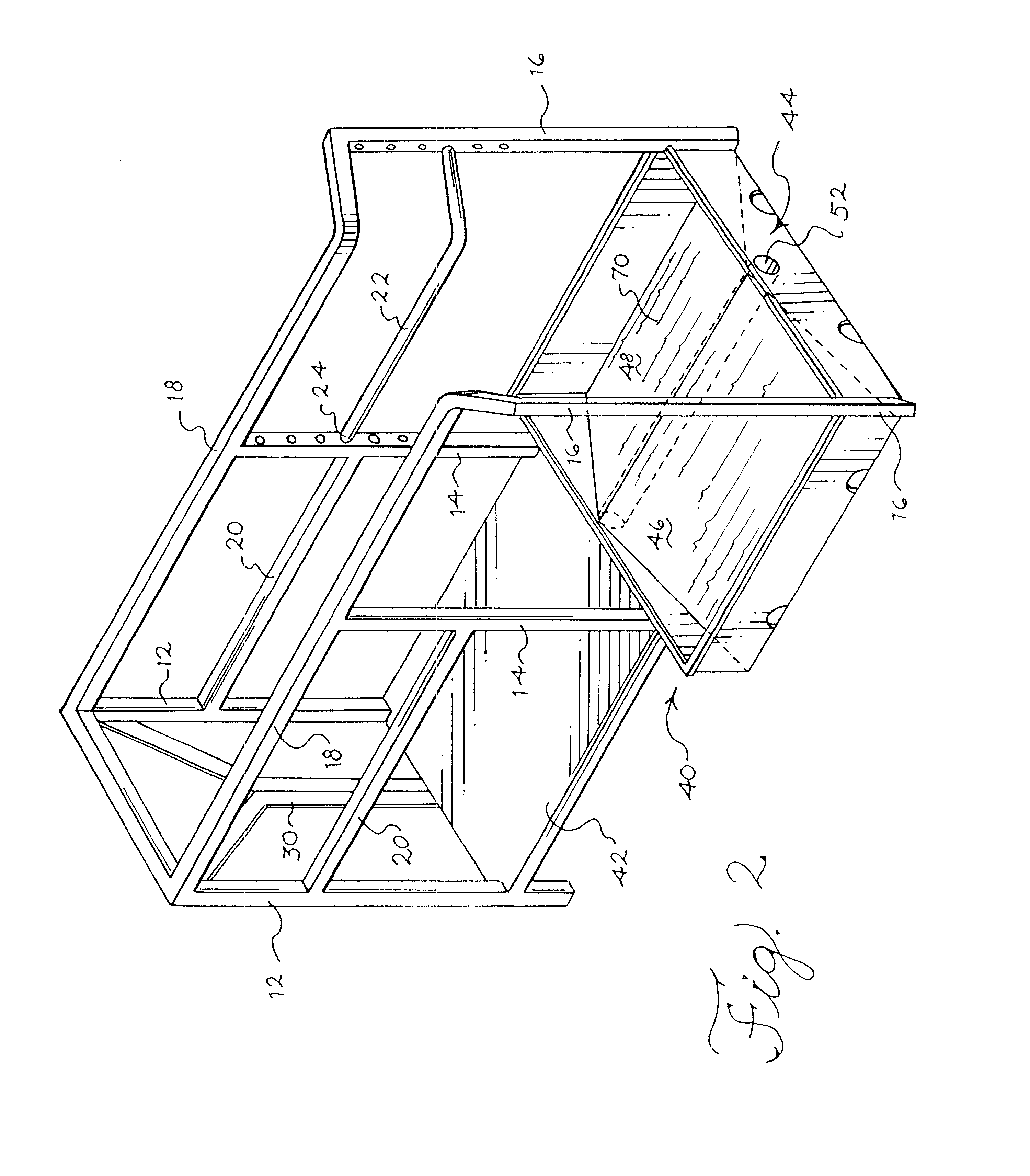
In FIG. 1 a conventional cattle crush 10 is shown with upright supports 12, 14 and 16 and side guide rails 18, 20 and 22. The side guide rails 16, 20, 22 are secured to the upright supports 12, 14, 16 by suitable fastening devices 24, such as nut and bolt assemblies. The height of the side guide rails can be altered accordingly by means of the fastening devices depending upon the size of animal in the cattle crush.

The animal stands on the floor 40 of the cattle crush, and is held in position by means of gate crush jaws 30.

When the animal is held in position by the crush jaws 30, its front legs will be in the floor area 42, and its hind quarters will be located in the floor area 44. Specifically, the animal's hind feet will be astride the floor plate 50 and positioned at 46 and 48, respectively. An optional V-plate 49 is positionable on the plate 50 that serves to keep the animal's feet on either side of a central longitudinal axis of the crush 10.

The floor plate 50 forming part of t...


PUM


Abstract

A confinement device for a four-legged animal is provided. The confinement device comprises a frame to receive the animal and a floor plate for the rear legs of the animal. The floor plate is arranged such that it is stable only when both rear legs of the animal bear down on the floor plate.

Description

CLAIM FOR PRIORITYThe present application claims priority to PCT Application No. PCT / GB00 / 00837 filed Mar. 10, 2000, entitled "Animal Confinement Device," which claims priority to Great Britain Application No. 9905551.9, filed Mar. 11, 1999, and the entire disclosures of the above-referenced applications are herein incorporated by reference.The present invention relates to an animal confinement device, also referred to as a livestock control device, and in particular to a device for use in conjunction with other livestock retaining devices such as cattle crushes, lamb adopters, milking parlors or stables. The device of the present invention is designed for use on farms or in other situations where the control of livestock is required.DESCRIPTION OF THE RELATED ARTCattle crushes, lamb adopters, milking parlors, stables and other such devices are commonly found on farms where it is desirable to hold an animal firmly in a fixed position. Such devices usually entail restraining the anim...

Claims


Application Information

Patent Timeline
IPC IPC(8): A01K1/06A01K1/12A01K1/00A01K15/00A01K15/04
CPCA01K1/0613A01K1/12A01K15/04A01K1/0011
Inventor TAYLOR, WILLIAM
Owner TAYLOR WILLIAM
Why Eureka
Try Eureka