Method for reducing braking distance

a technology of braking distance and braking function, which is applied in the field of brake system, can solve the problems of driving the control function, unable to achieve the maximum of the vehicle deceleration without unintentional deactivation of the automatic brake action, and having to carry out the control function of the driver

Inactive Publication Date: 2002-10-29
CONTINENTAL TEVES AG & CO OHG
View PDF36 Cites 53 Cited by
  • Summary
  • Abstract
  • Description
  • Claims
  • Application Information

AI Technical Summary

Problems solved by technology

In case of this well-known process it is disadvantageous that the driver must carry out a control function that is unusual when driving a vehicle, meaning he / she has to operate a switch with the left foot and one hand, respectively.
As a result an unintentional deactivation of the automatic brake action may be caused.
On the other hand the automatic brake action may be triggered unintentionally by a driver reacting quickly to a change in the driving situation causing a maximum of the vehicle's deceleration without this being necessary or desired.
In certain driving situations such a surprising, unintentionally strong braking may result in an disturbance of the traffic flow, particularly in case of dense lines of traffic, or it may even case an accident with a following vehicle.
Although it is simple for the driver of a corresponding vehicle to opoperate this well-known process for shortening the braking distance in his usual way, it may, however, in certain situations result in an unintentionally too low or too high a deceleration of the vehicle.
Thus the driver does not always have the complete control of his / her vehicle.
In accordance with the danger potential the amplification factor of the brake servo unit is increased in a dangerous situation.

Method used


Image

  • Method for reducing braking distance
  • Method for reducing braking distance
  • Method for reducing braking distance

Examples


an embodiment example

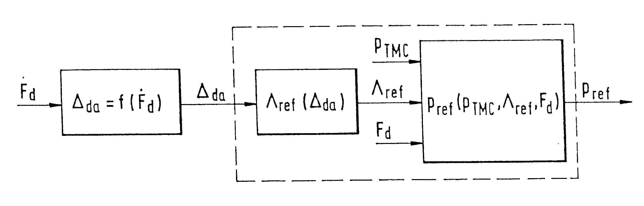
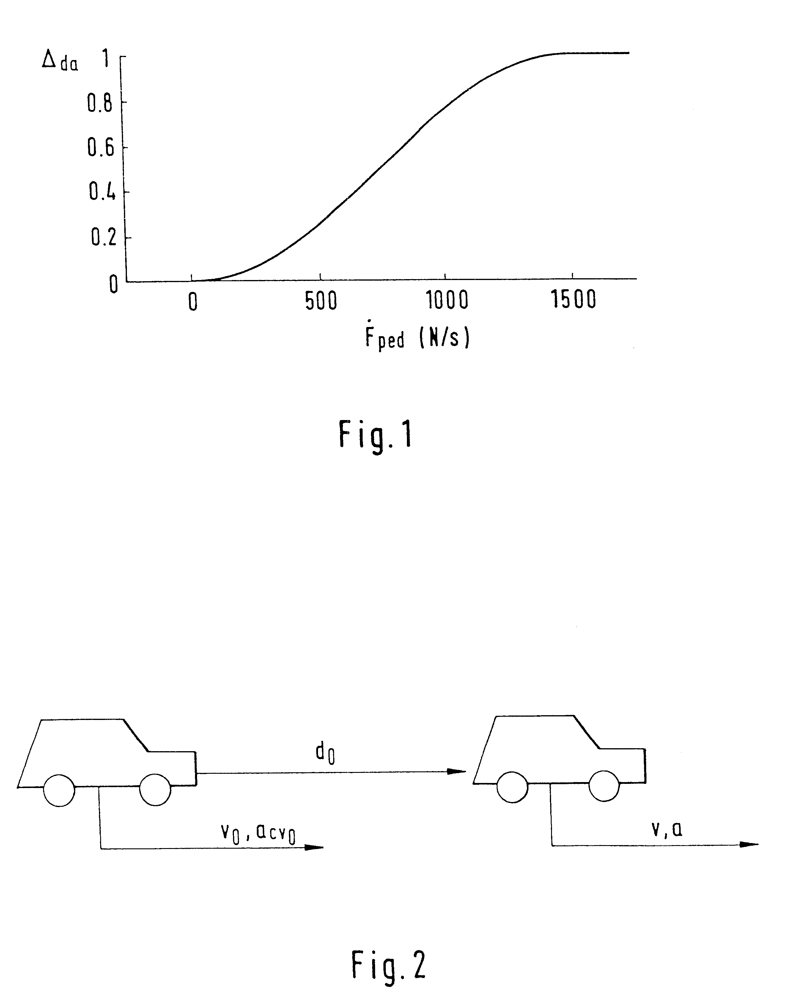
for determining the driver danger potential .DELTA..sub.da is described below; at the same time the driver danger potential .DELTA..sub.da is determined out of the change in the brake pedal force F.sub.ped. It has actually been proved that in normal driving situations changes in the brake pedal force of up to 200 N / s are practiced by the driver, whilst in danger situations the changes in the brake pedal force may reach 1500 N / s or more. These values depend very much on the driver; in danger situations some drivers may even practice changes in the brake pedal force of up to 8000 N / s. Since it is more likely that the people with a lower change in the brake pedal force do not brake sufficiently strongly, it is expedient to equate the driver danger potential .DELTA..sub.da for a change in the brake pedal force of 1500 N / s with 1 (.DELTA..sub.da =1). For a negative change in the brake pedal force the driver danger potential .DELTA..sub.da is equated with 0. Between the values 0 to 1500 N...


PUM


Abstract

The invention concerns a process for shortening the braking distance of a vehicle equipped with a brake servo unit which during a standard braking action is only triggered by the brake pedal pressure caused by the driver and in case of a critical driving situation is so triggered by a control device that in comparison to the standard braking action an increased amplification factor is set at the brake servo unit. The invention distinguishes itself by the fact that a danger potential is determined, stating the probability that the vehicle to be braked will be involved in an accident and that the increase of the amplification factor is controlled in accordance with the danger potential.

Description

TECHNICAL FIELDThe invention generally relates to brake systems and more particularly relates to a process for shortening the braking distance of a vehicle.BACKGROUND OF THE INVENTIONA process for shortening the braking distance is well-known from DE 89 11 963 U1 where on the basis of two present signals a pre-braking action is started for a duration of approx. 0.5 s. At the same time the first signal is triggered by the driver activating a switch. This switch is so arranged that it is either operated by the left foot or one hand and in case of the manual operation the switch is preferably so arranged that the hand does not have to be removed from the steering wheel. The second signal is triggered by recording the speed the driver uses to remove his foot from the accelerator. If this speed is above a certain threshold value pre-braking is automatically started.In case of this well-known process it is disadvantageous that the driver must carry out a control function that is unusual w...

Claims


Application Information

Patent Timeline
Patent Type & Authority Patents(United States)
IPC IPC(8): B60T7/22B60T8/32B60T7/12B60T8/17B60T13/72
CPCB60T7/12B60T7/22B60T8/3275
Inventor ECKERT, ALFREDBERTHOLD, THOMASTIELEMAN, ERWIN
Owner CONTINENTAL TEVES AG & CO OHG
Why Eureka
Try Eureka