
Power button controlled diagnostic mode for an information appliance

a technology of information appliances and diagnostic modes, which is applied in the direction of mechanical roughness/irregularity measurements, instruments, nuclear elements, etc., and can solve problems such as inability to boot pc, and bios might be corrupted

Inactive Publication Date: 2002-11-05
ADVANCED MICRO DEVICES INC
View PDF2 Cites 45 Cited by
  • Summary
  • Abstract
  • Description
  • Claims
  • Application Information

AI Technical Summary

Problems solved by technology

A problem with Flash ROMs, as well as updateable ROMs in general, is the potential that a BIOS might be corrupted when the BIOS is flashed.
A BIOS might be corrupted, for example, if power was interrupted during the flashing process.
In such a case, the PC would be unable to boot because its BIOS instructions would no longer be correct.
Legacy interfaces are considered "nondeterministic" because the operating system cannot guarantee correct installation of devices.
There exists little or no ability for hardware enumeration to allow the operating system to configure and control the devices.
Since the boot-block code is limited to about 8K of memory, there is not enough space in the boot block to connect such a device.
However, the new legacy-free design does not provide access to these devices during the boot block period.

Method used


Image

  • Power button controlled diagnostic mode for an information appliance
  • Power button controlled diagnostic mode for an information appliance
  • Power button controlled diagnostic mode for an information appliance

Examples


Embodiment Construction

The following related patent application is hereby incorporated by reference as if set forth in its entirety:

U.S. patent application, Ser. No. 09 / 542,220, entitled INFORMATION APPLIANCE DATA COMMUNICATION VIA AUDIO INTERFACES, filed concurrently.

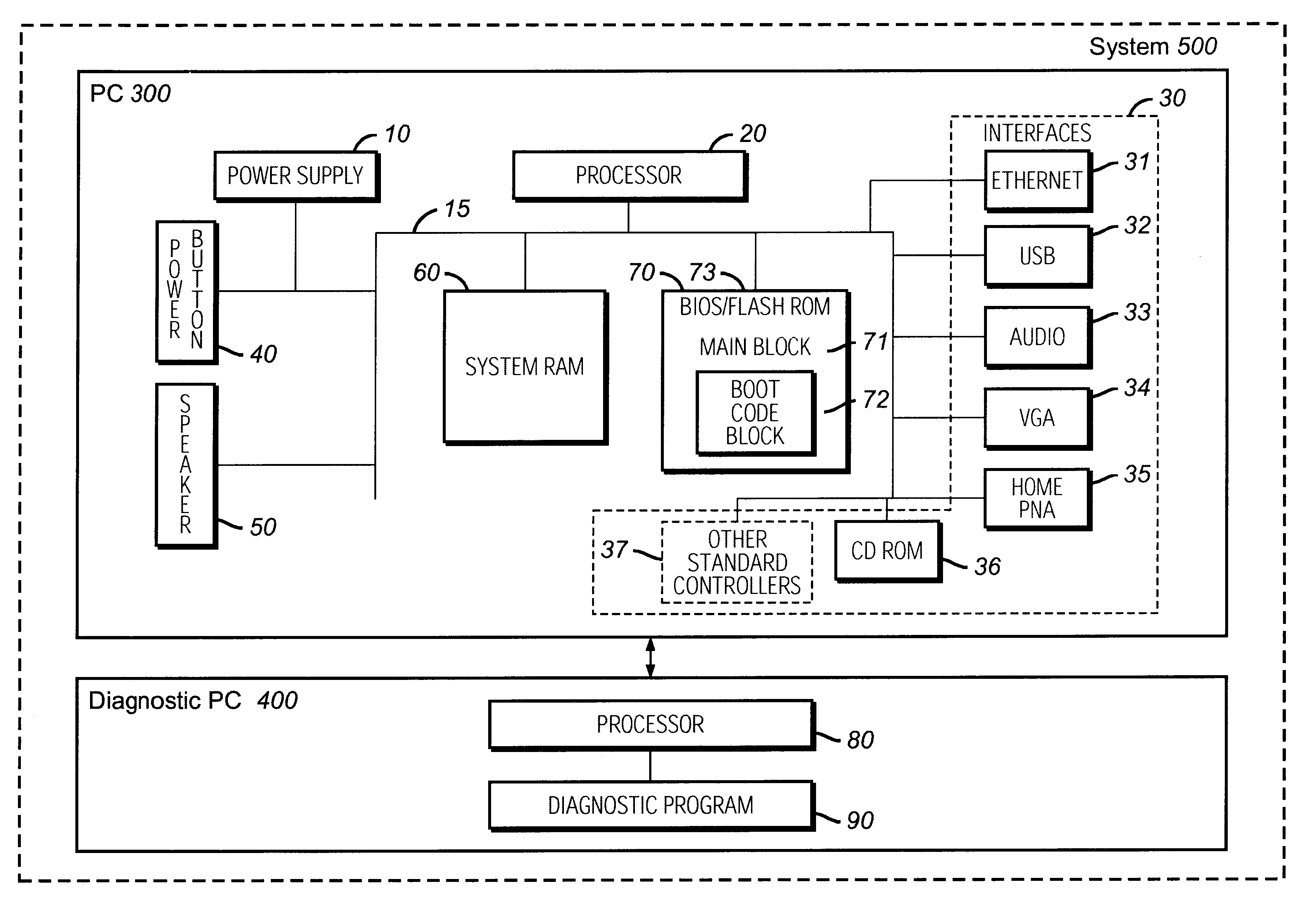
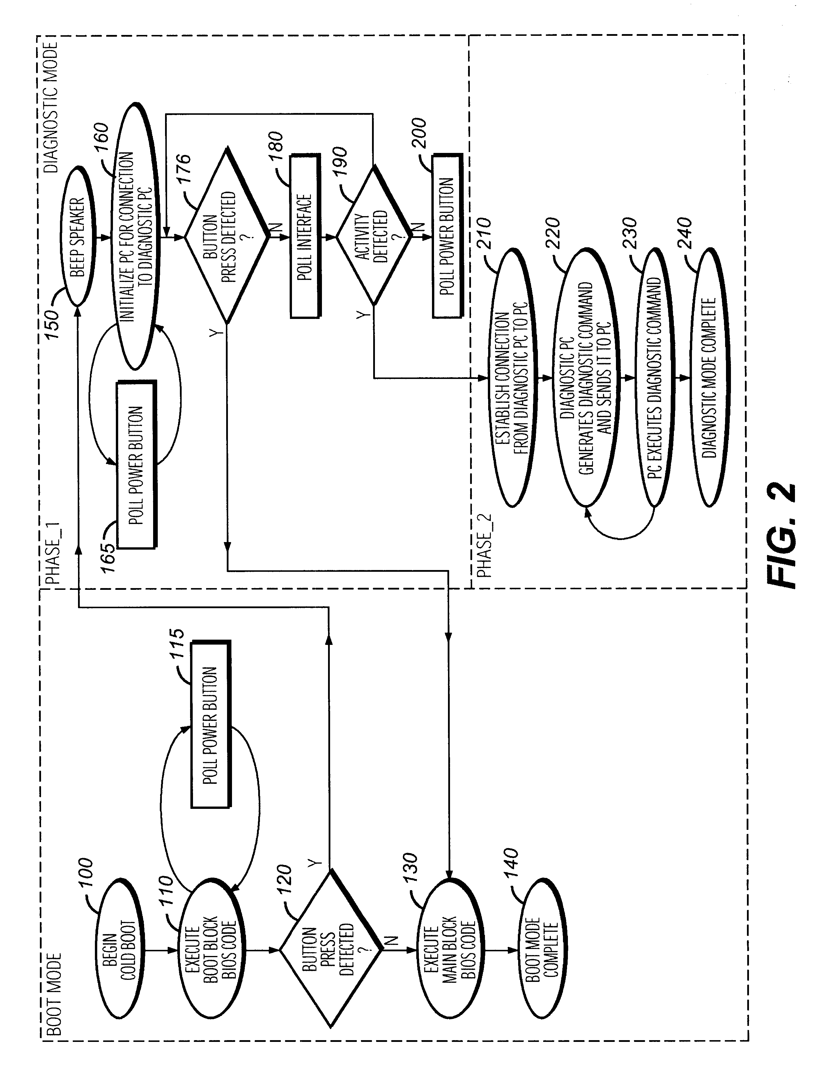
FIGS. 1 and 2, illustrate a typical computer system 500 implemented according to the invention. For purposes of explanation, specific embodiments are set forth to provide a thorough understanding of the present invention. However, it will be understood by one skilled in the art, from reading the disclosure, that the invention may be practiced without these details. Further, although the embodiments are described including a legacy-free PC, most, if not all, aspects of the system illustrated apply to interfacing an information appliance in combination with at least one diagnostic information source, where the information appliance contains a power button. Moreover, well-known elements, devices, process steps, and the like, are not set forth i...


PUM


Abstract

A system adds functionality to a power button where use of the power button controls the entry and exit from a diagnostic mode. The system includes an information appliance connected to a diagnostic appliance. Once an information appliance is powered up, the information appliance monitors its power button for a press which indicates a request to enter a diagnostic mode. Absent a press of the power button, the system continues to be under control of the information appliance and never enters a diagnostic mode. However, if a press of the power button is detected, the system enters a diagnostic mode. Once in a diagnostic mode the system provides an exit therefrom by interpreting a power button press as a request to exit. The window of time to make such an exit closes once the diagnostic appliance achieves communication with the information appliance. If the power button is pressed during this window of time, then the system ends its diagnostic mode and control of the system returns to the information appliance. If the power button is pressed after the window of time has closed, then the diagnostic appliance retains control of the information appliance and maintains its ability to execute diagnostic type commands thereon. The illustrative system is particularly useful when incorporated into devices with limited interface connections such as legacy-free information appliances. The system allows for a standard existing button on the information appliance to serve diagnostic purposes, avoiding the need for initializing peripherals requiring substantial execution space.

Description

1. Field of the InventionThe invention relates to the utilization of a power button of an information appliance to control the entry and exit into a diagnostic mode within a system comprised of an information appliance connected to a diagnostic information source.2. Description of the Related ArtPersonal Computer (PC) manufacturers have long been concerned with customer satisfaction. Manufacturers have learned customer satisfaction can be increased by reducing the number of required outside technician service calls. As a result, PC manufacturers have continued to pursue PC designs which reduce such service calls.Historically, Read Only Memory (ROM) has not been in-system updateable. ROM has generally required the assistance of outside technicians to update its contents. ROM typically holds the initialization code, operating system code and related data. The Basic Input / Output System (BIOS), part of the initialization code, is usually located in the ROM. Over the years, as system enh...

Claims


Application Information

Patent Timeline
IPC IPC(8): G06F13/10G06F11/22
CPCG06F11/2284
Inventor MAUPIN, PATRICK E.TOBIAS, DAVID F.
Owner ADVANCED MICRO DEVICES INC
Learn More