Dispenser-maker interface and method of use

Inactive Publication Date: 2002-11-12
BUNN O MATIC
View PDF14 Cites 59 Cited by
  • Summary
  • Abstract
  • Description
  • Claims
  • Application Information

AI Technical Summary

Benefits of technology

An object of the present invention is to provide a novel brewing substance dispenser, beverage maker and funnel interface which utilizes a funnel which can be mounted on the brewing substance dispenser and the beverage maker to communicate information regarding beverage batch size and/or type from

Problems solved by technology

This system might not be explicit regarding setting the switches on the coffee grinder and on the coffee brewer to achieve the desired results and confusion may result.
This confusion may occur if the user is preoccupied or busy.
Also, this system is complicated when a dual head coffee brewer is used with a dual hopper coffee grinder, and when a single coffee grinder services more than one coffee brewer

Method used


Image

  • Dispenser-maker interface and method of use
  • Dispenser-maker interface and method of use
  • Dispenser-maker interface and method of use

Examples


first embodiment

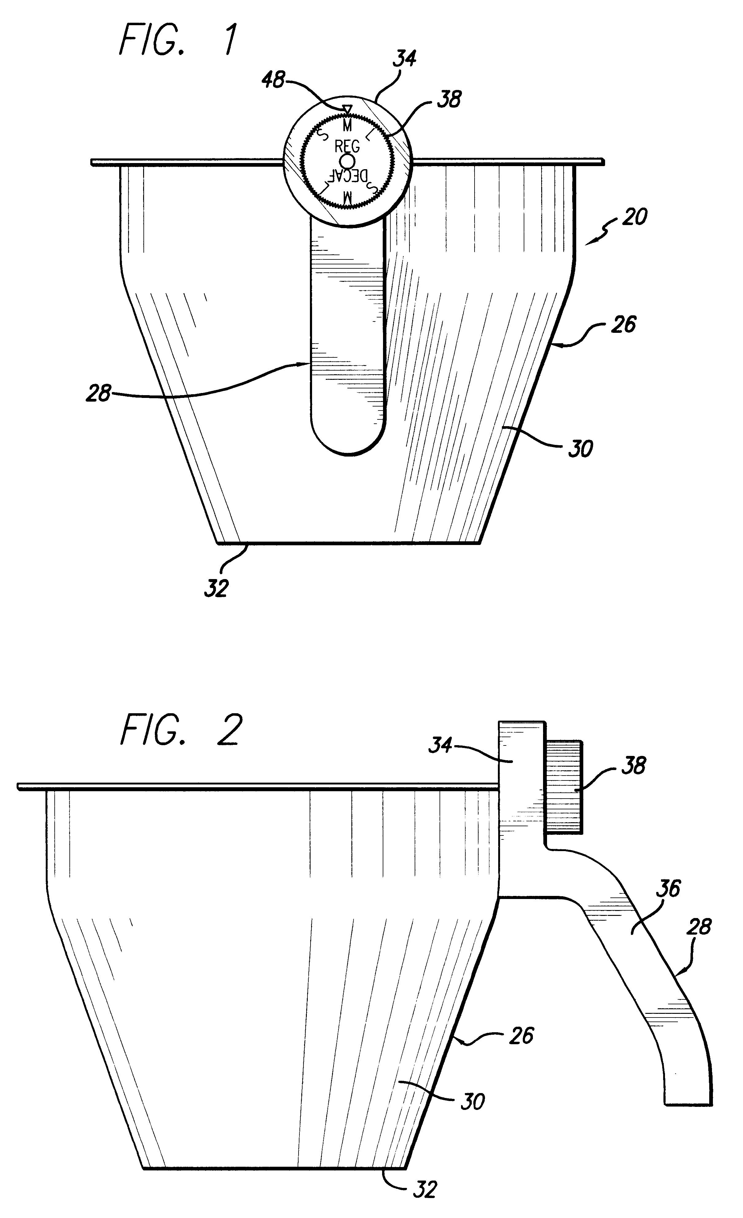
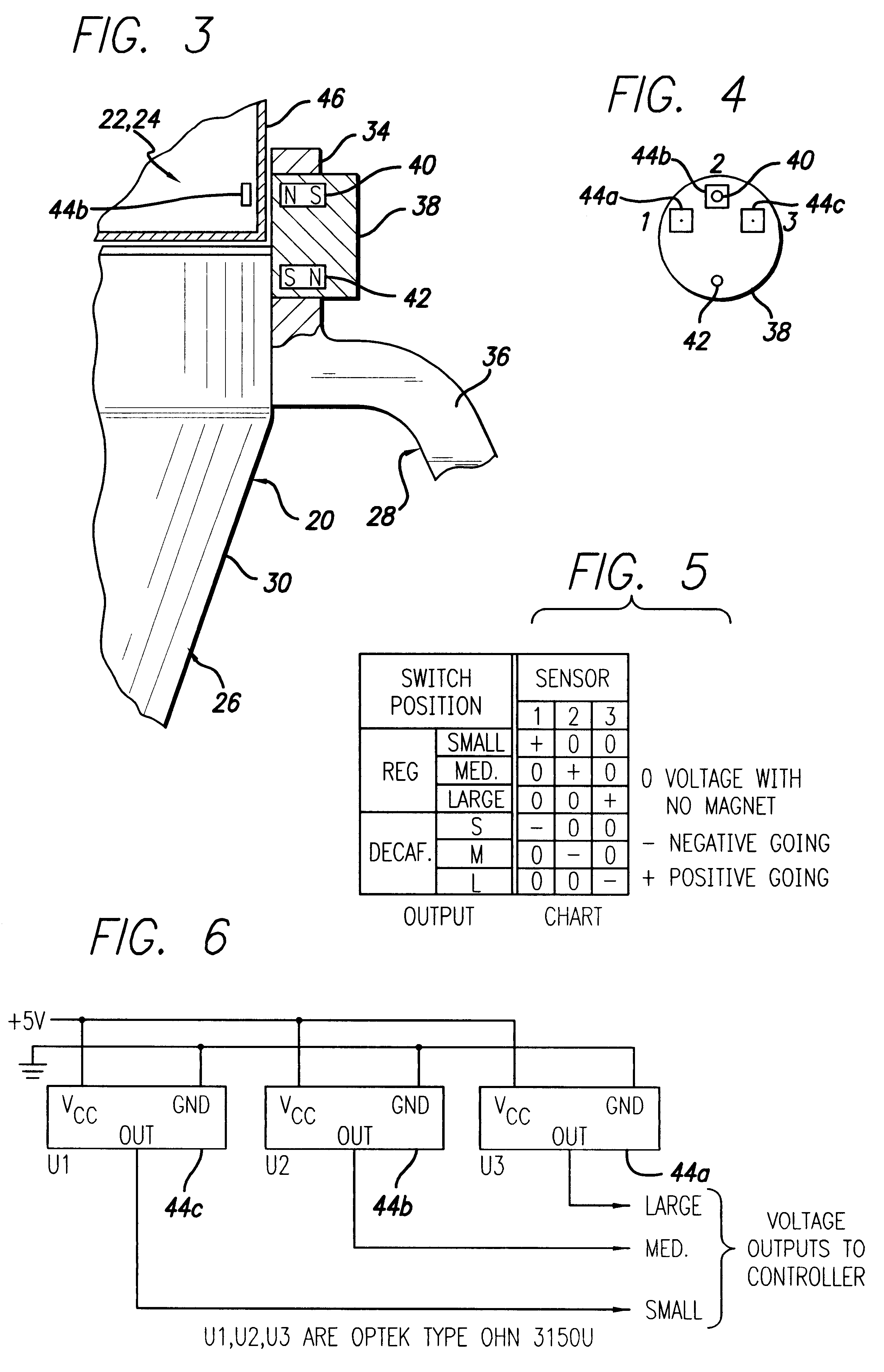
Attention is directed to the selector 38. As shown in FIGS. 1-4, the selector 38 takes the form of a knob 38 having a pair of imbedded magnets 40, 42. The knob 38 is rotatably mounted on the handle 28 by conventional means. The knob 28 has an upper portion which extends upwardly from the uppermost end of the body 26 and a lower portion which overlaps the upper end of the body 26. The pair of magnets 40, 42 are imbedded within the knob 38 proximate to the side wall 30 of the body 26 and are diametrically opposed to each other on the knob 38. Magnet 40 is mounted such that its north pole (N) is proximate to the side wall 30 of the body 26 and the south pole (S) is positioned away from the side wall 30 of the body 26. Magnet 42 is oppositely mounted such that its south pole (S) is proximate to the side wall 30 of the body 26 and the north pole (N) is positioned away from the side wall 30 of the body 26.

The exterior surface of the knob 38 has a plurality of indicia thereon, see FIG. 1. ...

second embodiment

Attention is directed to the selector 38a. As shown in FIGS. 7-10, the selector 38a takes the form of a slide switch assembly 50 which has a pair of imbedded magnets 52, 54. The slide switch assembly 50 includes a housing 56 which is mounted on the upper portion 34 of the handle 28 and a slide member 58 which is mounted thereto.

The housing 56 includes a rear wall 60, opposite side walls 62 which extend perpendicularly to the rear wall 60, a top wall 64 which extends perpendicularly to the rear wall 60, and a front wall 66 which is parallel to the rear wall 60 and is connected to the side walls 62 and to the top wall 64. The front wall 66 has a cutout 68 therein in which a cover 70 is mounted by suitable means. The cover 70 covers a portion of the cutout 68, such that a slot 72 is provided between the bottom of the cover 70 and the front wall 66. Upper and lower rail portions 74, 76 protrude outwardly from a bottom section of the rear wall 60 and are perpendicular thereto such that t...

fourth embodiment

Attention is invited to the present invention as shown in FIGS. 16 and 17.

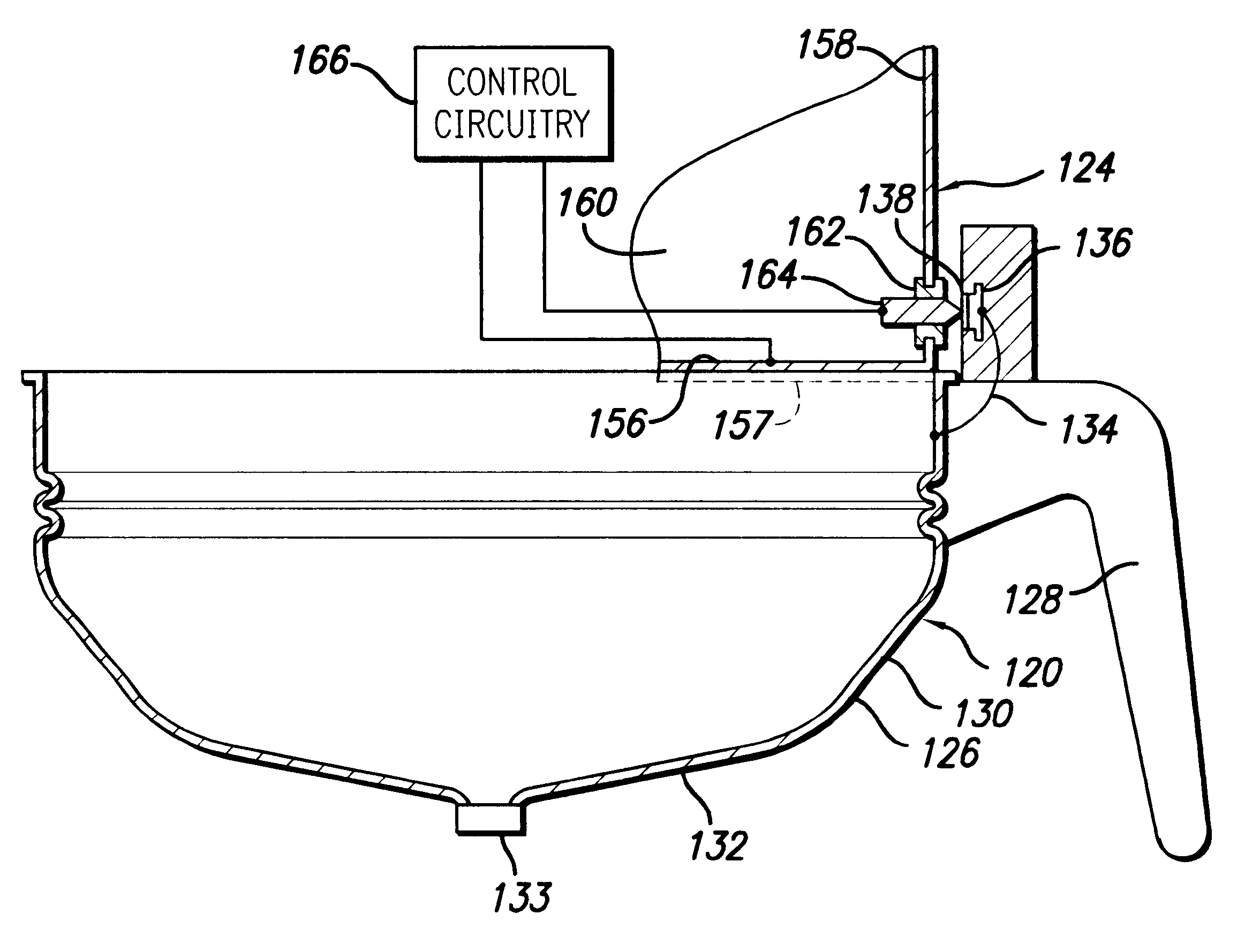
The memory device 136a is implanted in the housing 134a such that it is encapsulated within the housing 134a. An example of a suitable memory device 136a is an RFID device manufactured by Temic. This type of device transfers information by electromagnetic coupling and does not require an electrical contact to transfer information.

As shown in FIG. 16, the brewing substance dispenser 122a, such as coffee grinder, has a metal bottom wall 168, a metal front wall 170, opposite side walls 172 (only one of which is shown) and a top wall (not shown). A pair of funnel mounting rails 171 (only one of which is shown in phantom line) are provided on the bottom wall 170. The rails 171 may be formed from stainless steel or other suitable conductive material. The front wall 170 has an aperture provided therethrough. A plastic insert 174, which is transparent to electromagnetic energy, is mounted within the aperture. A reader...


PUM


Abstract

An interface for a beverage dispenser, a maker and a funnel and its method of use is provided. The dispenser has a structure therein for storing and transmitting information and a user interface coupled thereto. The funnel includes a body and a memory device therein. The maker includes structure for reading the memory device of the funnel. When the funnel is mounted on the dispenser, the structure in the dispenser and the memory device of the funnel are in communication with each other so that information input into the dispenser by a user is transmitted to the funnel. The appropriate beverage is dispensed into the funnel. Thereafter, when the funnel is mounted on the maker, the structure in the maker and the memory device of the funnel are in communication with each other and the structure in the maker reads the information stored in the memory device of the funnel so that the desired beverage can be produced.

Description

This invention is generally directed to a novel beverage substance dispenser, beverage maker or brewer and funnel interface and its method of use. More particularly, the invention contemplates a novel interface which utilizes a funnel which can be mounted on either a brewing substance dispenser, such as a coffee grinder, or a beverage maker, such as a coffee brewer, to communicate information regarding beverage batch size and / or type of beverage from the brewing substance dispenser to the beverage maker.U.S. Pat. No. 5,186,399, which identifies the same assignee as the present application, describes a system of connecting a multiple batch size brewer and a dual hopper grinder in order to coordinate the amount of ground coffee with the selected brewing volume. This system might not be explicit regarding setting the switches on the coffee grinder and on the coffee brewer to achieve the desired results and confusion may result. This confusion may occur if the user is preoccupied or bus...

Claims


Application Information

Patent Timeline
IPC IPC(8): A47J42/38A47J42/00A47J31/42A47J31/06
CPCA47J31/0621A47J31/42A47J42/38
Inventor KNEPLER, JOHN T.
Owner BUNN O MATIC
Why Eureka
Try Eureka