Prefabricated plastic shed and components therefor

a prefabricated, plastic shed technology, applied in the direction of cellulosic plastic layered products, walls, transportation and packaging, etc., can solve the problems of increasing the cost of installation and time-consuming and labor-intensive conventional window or door trims, and achieve the effect of reducing installation costs

Inactive Publication Date: 2002-11-19
ROYAL GROUP
View PDF4 Cites 41 Cited by
  • Summary
  • Abstract
  • Description
  • Claims
  • Application Information

AI Technical Summary

Benefits of technology

The present invention provides a new type of trim member that has a single design which includes multiple parts. This helps keep everything organized and easy to install without requiring extra steps or special skills. It also saves money because it doesn't have to be assembled separately like traditional windows.

Problems solved by technology

The technical problem addressed in this patent text needs to be identified by a senior R&D person who has read it through.

Method used


Image

  • Prefabricated plastic shed and components therefor
  • Prefabricated plastic shed and components therefor
  • Prefabricated plastic shed and components therefor

Examples


Embodiment Construction

:

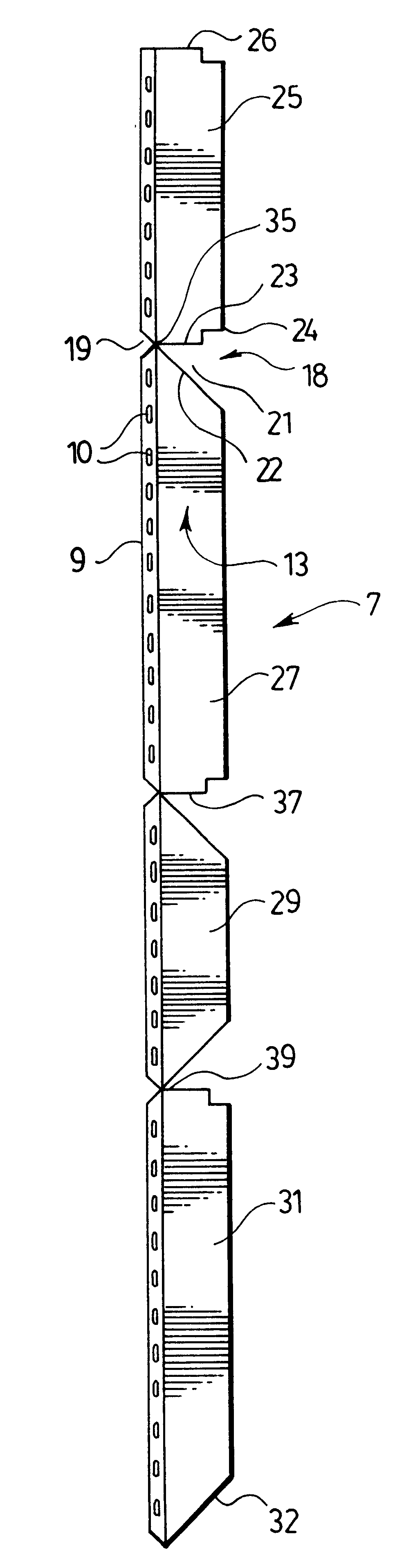
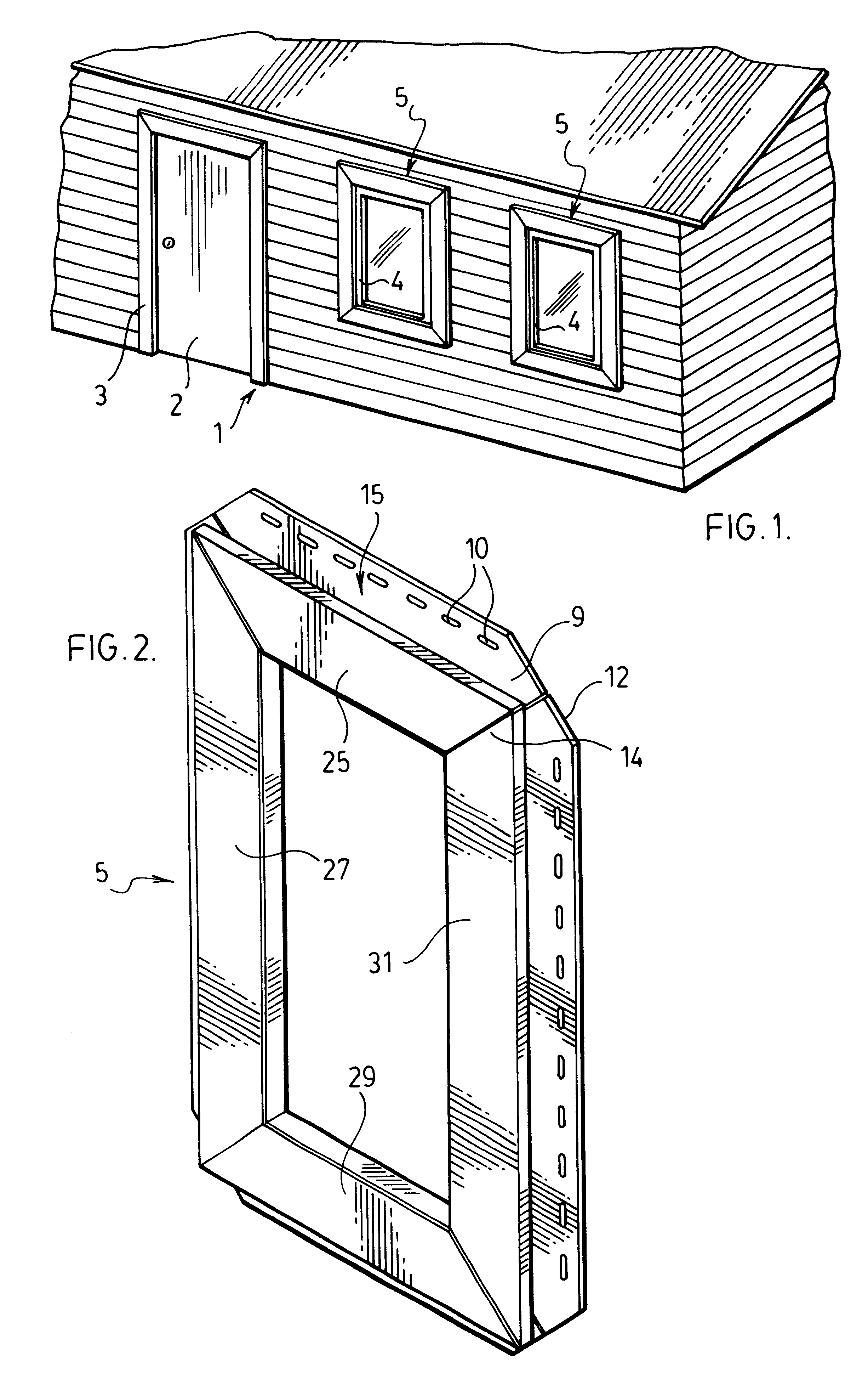
FIG. 1 shows a building generally indicated at 1. This building has a door 2 surrounded by a trim border 3 and windows each having a window frame 4 which is surrounded by a window trim border 5. These trim borders are not used for holding the door or the window frame within the building wall, but rather add a decorative appearance around the door and windows.

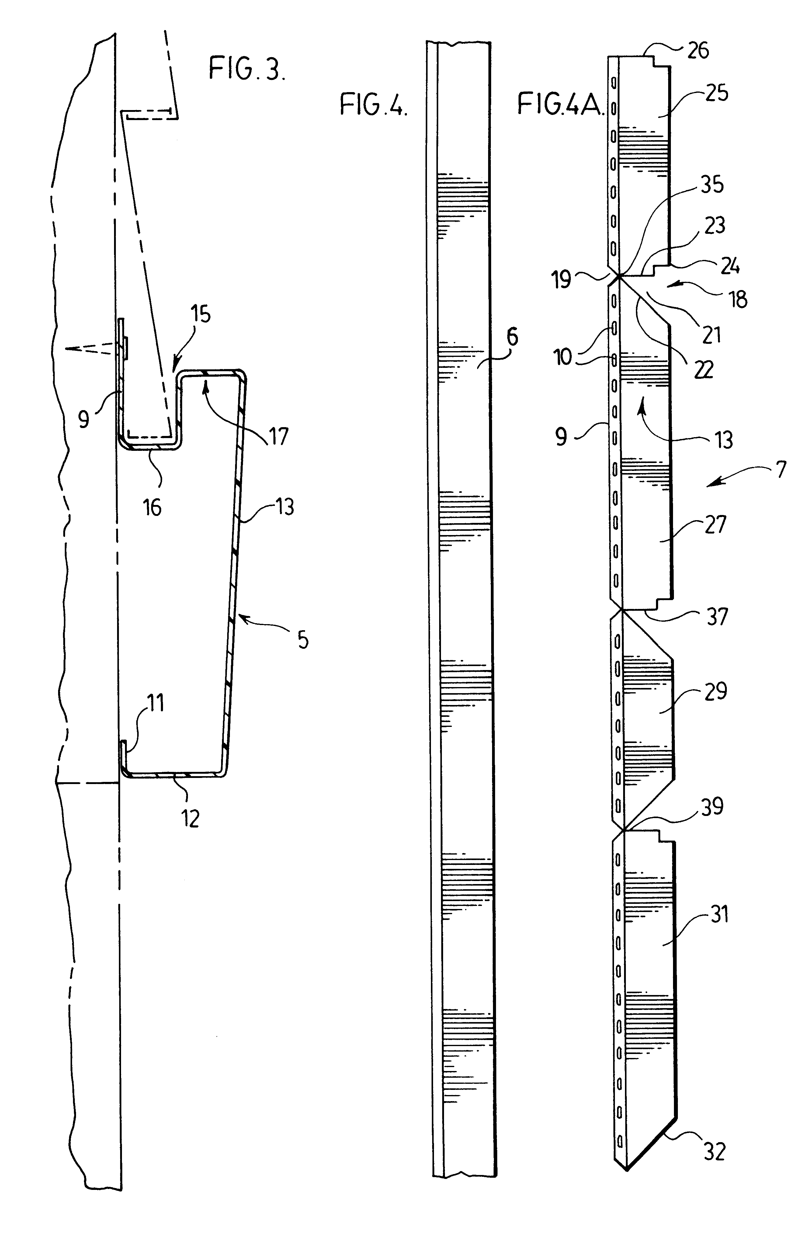
According to an aspect of the invention, which will be described later in detail, the border trim does provide a function with respect to edge covering of panelling on the building wall and in particular the edge covering of a vinyl siding.

The trim border can be made from various different materials and by different methods of manufacture. For example, the trim border can be made from aluminum or steel, either extruded or rolled, or it can be made from different plastics such as foamed or rigid polyvinyl chloride. Extruding PVC allows the trim member used to form the border to be made with great accuracy in an extrusion process...


PUM

PropertyMeasurementUnit
Angleaaaaaaaaaa
Angleaaaaaaaaaa
Areaaaaaaaaaaa

Abstract

A trim member is made from a single piece of trim material. The trim material has a plurality of spaced apart cut out regions which divide the trim member into a plurality of trim sections. These trim sections are connected to one another by thin strips of the trim material in each cut out region. The strips are bendable and the cut out regions are shaped to enable a reconfiguring of the trim member from a lineal to a trim border forming configuration for use around a door, a window or a windowed wall area of a building wall.

Description


Claims


Application Information

Patent Timeline
Owner ROYAL GROUP
Why Eureka
Try Eureka