
Low profile shunting pv interconnect for solar roofing

Inactive Publication Date: 2009-08-27
REDWOOD RENEWABLES
View PDF5 Cites 67 Cited by
  • Summary
  • Abstract
  • Description
  • Claims
  • Application Information

AI Technical Summary

Benefits of technology

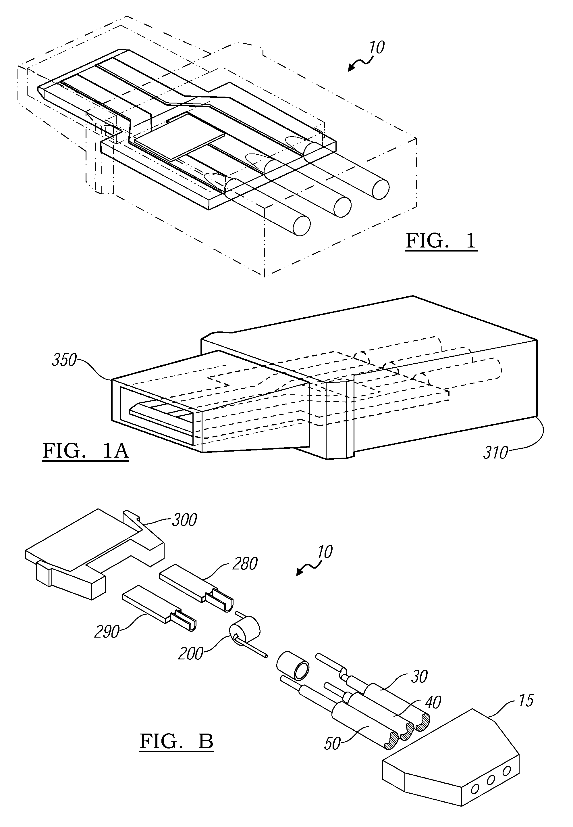
[0006]The invention provides the technology that will enable the expanded use of PV roofing tiles by significantly lowering the cost and improving the aesthetics of system installations. The terminology PV will be used extensively throughout and is to be understood as Photovoltaic or as a solar energy converting cell or simply as solar. This invention is a low profile electrical and interconnection system with plug connectors under 10 mm in height, with a built in shunting or bypass diode and circuit that allows current to be shunted around high impedance PV modules. This system improves on the current technology by reducing the system cost and increasing the system reliability.
[0007]The novel integration of a shunting or bypass diode is the cornerstone of a completely integrated PV roofing tile system, thus significantly improving the systems' operation and performance by reducing the effect of a single module's reliability. Without the need for special roof decking the installation cost of the novel low profile shunting PV roofing tile interconnection system is significantly reduced to that of current technology. Maintenance and repair is also improved with the integrated solar tile design, allowing for ease of replacement and repair.

Problems solved by technology

None of the available plugs have a built in shunting or bypass diode.
This condition has blocked the increased use of solar installations on roofs, because the current technology doesn't allow the solar tiles to be aesthetically laid flat on the roofing substrate without significantly increasing the cost of installation with special roof decking.
If the tiles are laid flat directly on the roof decking, the existing technology is highly susceptible to tile warping and will not pass a wind test.

Method used


Image

  • Low profile shunting pv interconnect for solar roofing
  • Low profile shunting pv interconnect for solar roofing
  • Low profile shunting pv interconnect for solar roofing

Examples


Embodiment Construction

[0025]While describing the invention and its embodiments, various terms will be used for the sake of clarity. These terms are intended to not only include the recited embodiments, but also all equivalents that perform substantially the same function, in substantially the same manner to achieve the same result.

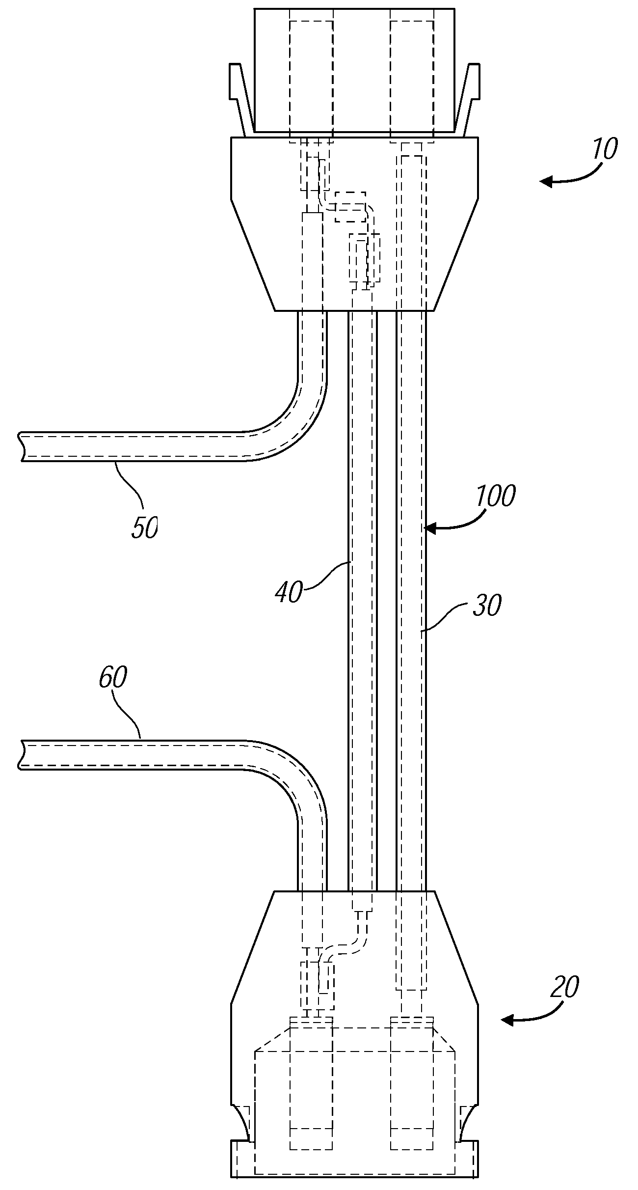
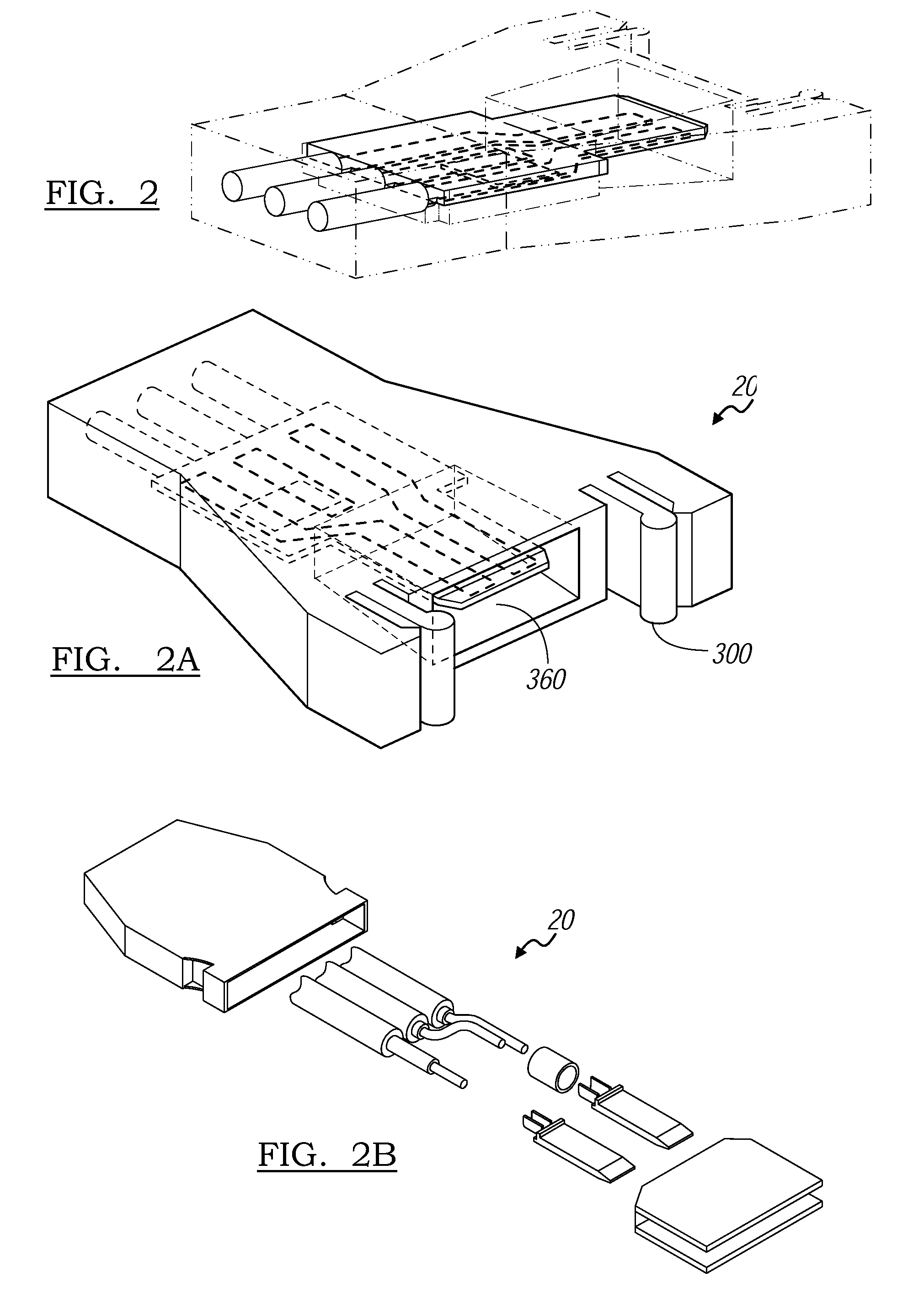
[0026]A preferred embodiment of the present invention discloses a low profile shunting PV interconnection system for use with PV roofing tiles depicted in top plan view in FIG. 3 and indicted generally by the reference number 100 and shall be referenced with the abbreviated terminology as the interconnection system. The interconnection system 100 is comprised of a male interconnect plug 10, a female interconnect socket 20 that are electrically connected by three wires, a return line wire 30, a bypass wire 40, and either the positive solar cell lead wire 50 or the negative solar cell lead wire 60.

[0027]FIG. 7 depicts the bottom plan view of several PV roofing tiles 110. They are...


PUM


Abstract

A low profile integrated solar roofing tile connecting system for the formation of a solar roof. The system is aesthetically appealing because the tiles lay relatively flat with a very low profile without any bulges or ridges because all wires and connectors embedded in the tiles. This low profile optimizes the roof's ability to withstand wind loads as well as minimizes cracking or breaking of the tiles due to external load forces. The connectors produce uniform spaces between adjacent tiles as well as providing an easy way to extend or exchange tiles. An integrated shunting or bypasses diode provides a current shunt path in the event of a modules' impedance upsurge cause by shading or by non-functioning tiles. This also allows for the flexible arrangement of the PV roofing tiles for a variety of system configurations, e.g. grid-tied, and off-grid systems, while maintaining system reliability and a modularized design.

Description

PRIORITY FILING[0001]This application is claiming the filing date of Feb. 22, 2008 of provisional patent application Ser. No. 61 / 066,813.BACKGROUND OF THE INVENTION[0002]1. Field of Invention[0003]The invention relates to the field of photovoltaic power (PV) systems design and applications, specifically PV roofing tiles. Additionally, it is foreseeable that this invention can be utilized in other application where low profile connection of electrical panels is desired, such as in flat panel lighting for example. This invention is a low profile electrical interconnect system with an integrated shunting or bypass diode that enables an aesthetic integrated solar tile system to be easily installed on sloped roofs without customized roof decking.[0004]2. Related Art[0005]In the field of solar interconnects the height of the existing interconnects ranges from 13.5 mm to 18.5 mm in height. These plugs have large snap on connectors, screw on locks or ribbed plugs. None of the available plug...

Claims


Application Information

Patent Timeline
IPC IPC(8): H01R13/629
CPCH01L31/02008H01R13/6641H02S20/25Y02E10/50Y02B10/12Y02B10/10
Inventor FAUST, THOMASHERBERT, JONATHAN CARTERCHEUNG, OSBERT
Owner REDWOOD RENEWABLES
Learn More