Photovoltaic solar cell module assembly, wiring system and photovoltaic power system
a photovoltaic solar cell and module technology, applied in the field of photovoltaic solar cell module assembly and wiring system thereof, can solve the problems of easy errors in counting the number of modules in series connection, increase in the number etc., and achieve the effect of facilitating the wiring connection of photovoltaic solar cell modules
- Summary
- Abstract
- Description
- Claims
- Application Information
AI Technical Summary
Benefits of technology
Problems solved by technology
Method used
Image
Examples
first embodiment
[0048] (First Embodiment)
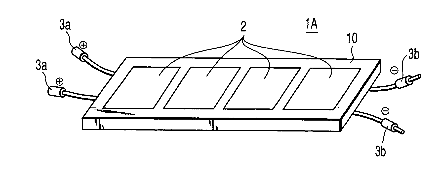
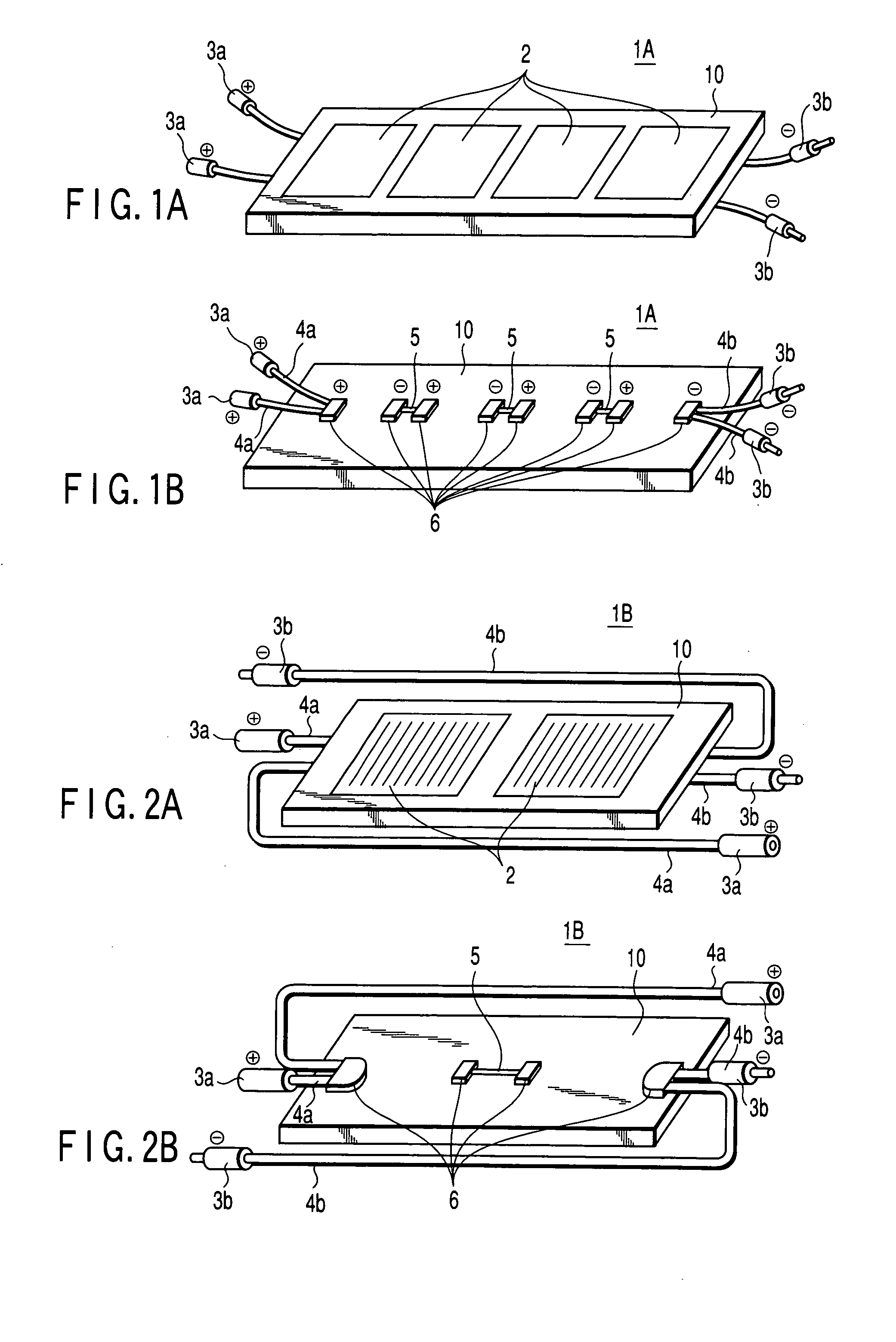
[0049]FIGS. 1A and 1B schematically show an example of a photovoltaic solar cell module assembly employed in a photovoltaic power system in which an operating voltage for each photovoltaic solar cell module is 50V and an operating voltage of a power conditioner is 200V. In a photovoltaic solar cell module assembly 1A of the first embodiment, four photovoltaic solar cell modules 2 are aligned on a common base member 10 as shown in FIG. 1A and connected in series as shown in FIG. 1B. Each of positive and negative terminals of both side ends is bifurcated. In other words, the positive terminal and the negative terminal inside a terminal box 6, of the adjacent photovoltaic solar cell modules 2, are connected in series by an inter-module coupling cable 6 and connectors. The bifurcated positive electrode cables 4a are connected to the positive terminal on a one-side end of the row of modules and the bifurcated negative electrode cables 4b are connected to the nega...
second embodiment
[0055] (Second Embodiment)
[0056]FIGS. 2A and 2B schematically show an example of a photovoltaic solar cell module assembly in a case where an operating voltage for each photovoltaic solar cell module is 100V and a power conditioner operating voltage is 200V. In a photovoltaic solar cell module assembly 1B of the second embodiment, two photovoltaic solar cell modules 2 are arranged adjacently as shown in FIG. 2A and connected in series as shown in FIG. 2B. A pair of positive and negative terminals are guided from each of the terminal boxes 6 of both side ends. In other words, the positive terminal and the negative terminal inside the terminal boxes 6, of the adjacent photovoltaic solar cell modules 2, are connected in series by the inter-module coupling cable 6 and connectors. The bifurcated positive and negative electrode cables 4a and 4b are connected to the positive and negative terminals on a one-side end of the row of modules and the bifurcated positive and negative electrode ca...
third embodiment
[0062] (Third Embodiment)
[0063] Next, a third embodiment of the present invention will be explained with reference to FIGS. 3, 4, 9A-9D, and 10A-10C.
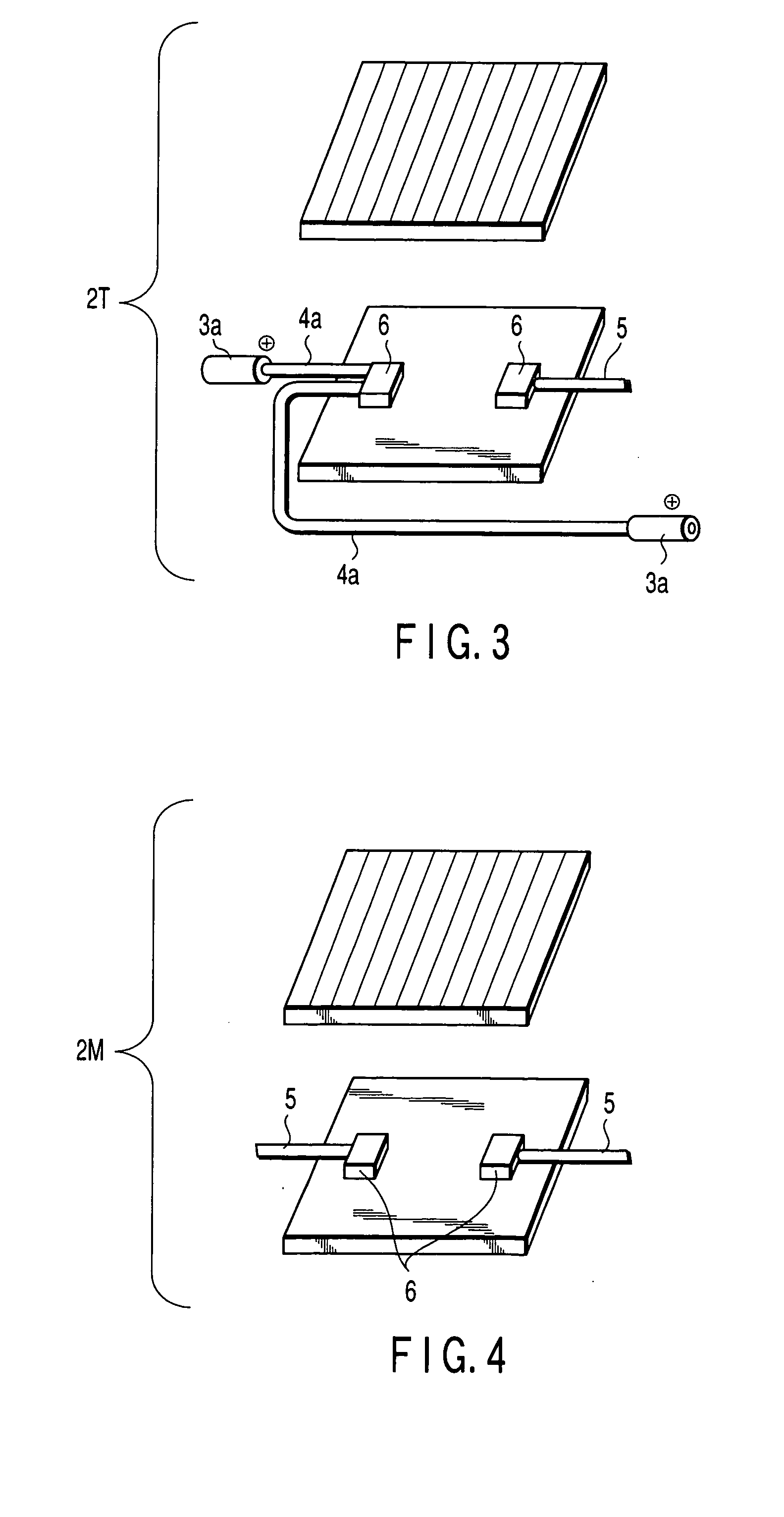
[0064]FIG. 3 schematically shows a photovoltaic solar cell module arranged at an end portion of the photovoltaic solar cell module assembly. FIG. 4 schematically shows a photovoltaic solar cell module arranged at a portion (middle portion) other than the end portion of the photovoltaic solar cell module assembly.
[0065] In the photovoltaic solar cell module assembly of this embodiment, photovoltaic solar cell module 2T shown in FIG. 3 is arranged on both side ends of the module assembly and photovoltaic solar cell module 2M shown in FIG. 4 is arranged at the middle portion of the module assembly. The photovoltaic solar cell modules 2M are connected with the inter-module coupling cable 5 and the modules 2T of both sides are connected to the modules 2M of the middle portion. Thus, the output voltage of 200V corresponding to the power con...
PUM
 Abstract
Description
Claims
Application Information
 - R&D
- Intellectual Property
- Life Sciences
- Materials
- Tech Scout
- Unparalleled Data Quality
- Higher Quality Content
- 60% Fewer Hallucinations
Browse by: Latest US Patents, China's latest patents, Technical Efficacy Thesaurus, Application Domain, Technology Topic, Popular Technical Reports.
© 2025 PatSnap. All rights reserved.Legal|Privacy policy|Modern Slavery Act Transparency Statement|Sitemap|About US| Contact US: help@patsnap.com


