Method for processing work pieces by removing material

a technology of material removal and work pieces, applied in the field of methods, can solve the problems of complex processing and other problems

Inactive Publication Date: 2002-11-26
STARRAG
View PDF7 Cites 19 Cited by
  • Summary
  • Abstract
  • Description
  • Claims
  • Application Information

AI Technical Summary

Problems solved by technology

In these methods the processing remains also still complicated in spite of the limited accuracy (danger of collision)

Method used


Image

  • Method for processing work pieces by removing material
  • Method for processing work pieces by removing material
  • Method for processing work pieces by removing material

Examples


Embodiment Construction

In the following discussion, the present problem is first discussed from a mathematical point of view. Then different embodiments of the method according to the present invention are presented.

Tool

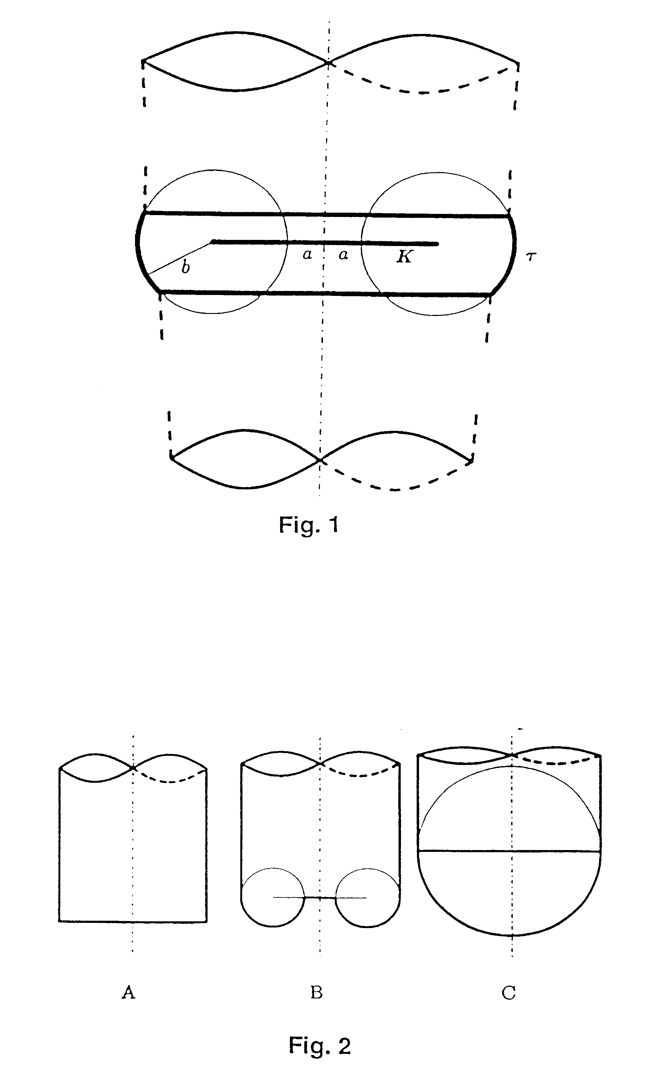
Discussed are rotationally symmetric tools, where a torus segment .tau. acts on the workpiece as it is shown in FIG. 1, wherein the torus segment .tau. describes the cutting range of the tool, i.e. the range within which material of the workpiece is removed.

The tool can be any tool for machining by removal of material, such as a rotating milling cutter or the working electrodes of an apparatus for electro-erosive machining.

The large radius of the torus .tau. is designated by a, the small radius by b, and the torus center circle by K. A possible parameterization of the torus is: ##EQU1##

FIG. 2 shows typical examples: cylindric tools (a >0, b=0), torus tools (a>b>0) and spherical tools (a=0, b>0).

Spherical tools do not allow to improve the local fit quality because they lack a degree of free...


PUM

PropertyMeasurementUnit
tilting angleaaaaaaaaaa
areaaaaaaaaaaa
distanceaaaaaaaaaa

Abstract

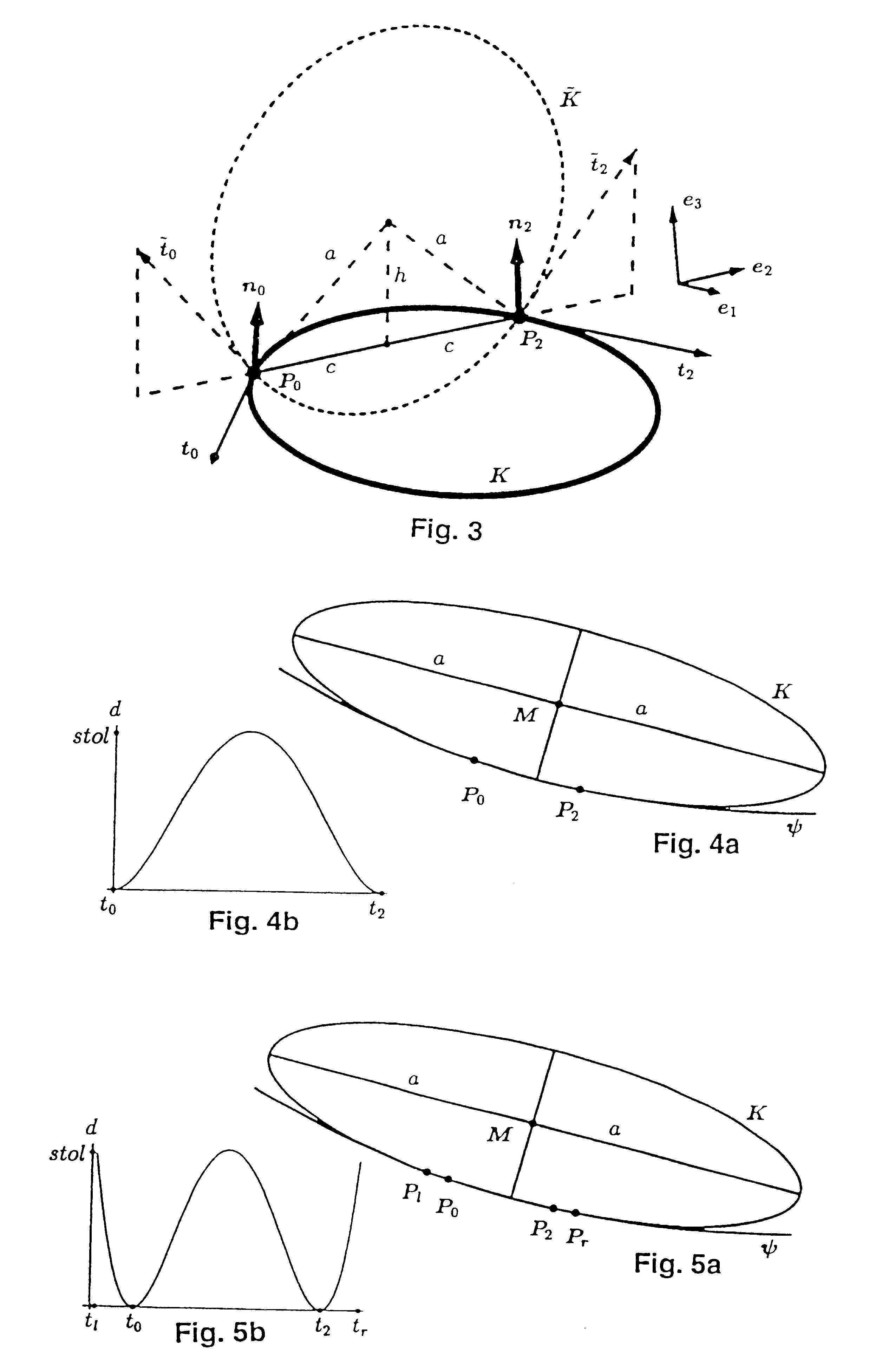
The invention relates to a method for processing a work piece by removing material with a tool in which the tool is guided over the work piece in paths. The pivoting and cambering angle of the tool is selected in every point such that the width of a tolerance zone is optimized. Within said zone, the effective zone (K) of the tool is located in a tolerance zone of the desired specified surface (Psi) of the work piece. The distance between two points (Pl, Pr) is maximized, said points characterizing the furthest outlying points of the tolerance zone. As a result, it possible to produce surfaces having a high precision with a small number of paths.

Description

The invention relates to a method for processing workpieces by removing material.Such methods serve e.g. for generating the paths of tools having five axes in CAD (Computer Aided Design) / CAM (Computer Aided Manufacturing) systems for the processing of workpieces with arbitrary surfaces.STATE OF THE ARTAll known methods for tool fitting start from from predefined contact paths of the tool on the workpiece. The position and orientation or the inclination angle (angle between the axis of the tool in the direction of movement of the tool and a vector normal to the desired surface) and the tilting angle (angle of the axis of the tool in the direction perpendicular to the direction of movement) are determined in different ways for selected points on the contact path. The presently best method (Jean-Pierr Kruth and Paul Klewais, Optimization and Dynamic Adaptation of the Cutter Inclination during Five-Axis Milling of Sculptured Surfaces, Annals of the CIRP, 1994) is based, for the determin...

Claims


Application Information

Patent Timeline
Patent Type & Authority Patents(United States)
IPC IPC(8): G05B19/41G05B19/4097G05B19/4099G05B19/4103
CPCG05B19/4099G05B19/41Y10T409/303808Y10T409/300896Y02P90/02
Inventor ENGELI, MAXWALDVOGEL, JORGSCHNIDER, THOMAS
Owner STARRAG
Why Eureka
Try Eureka