Adjustable socket rack with coaxial clamp

a technology of adjustable sockets and clamps, which is applied in the direction of tray containers, manufacturing tools, transportation and packaging, etc., can solve the problems of not meeting the requirements of very close tolerances and the inability of the leaf spring to adequately perform the function of the socket spring

Inactive Publication Date: 2002-12-03
RAMSEY EDWARD +1
View PDF15 Cites 95 Cited by
  • Summary
  • Abstract
  • Description
  • Claims
  • Application Information

AI Technical Summary

Problems solved by technology

While this prior system works quite well, it does require very close tolerances in the dimensions of the socket mount, the track, and the length of the screw.
As a result, the leaf spring will not adequately perform its function of holding a wrench socket on the socket peg.
Conversely, if the screw is too short or the distance between the bearing ledges and the bottom of the track is too great, the head of the screw will clamp the anchored end of the leaf spring against the top of the socket peg before the distal tip of the screw fully engages the track.

Method used


Image

  • Adjustable socket rack with coaxial clamp
  • Adjustable socket rack with coaxial clamp
  • Adjustable socket rack with coaxial clamp

Examples


Embodiment Construction

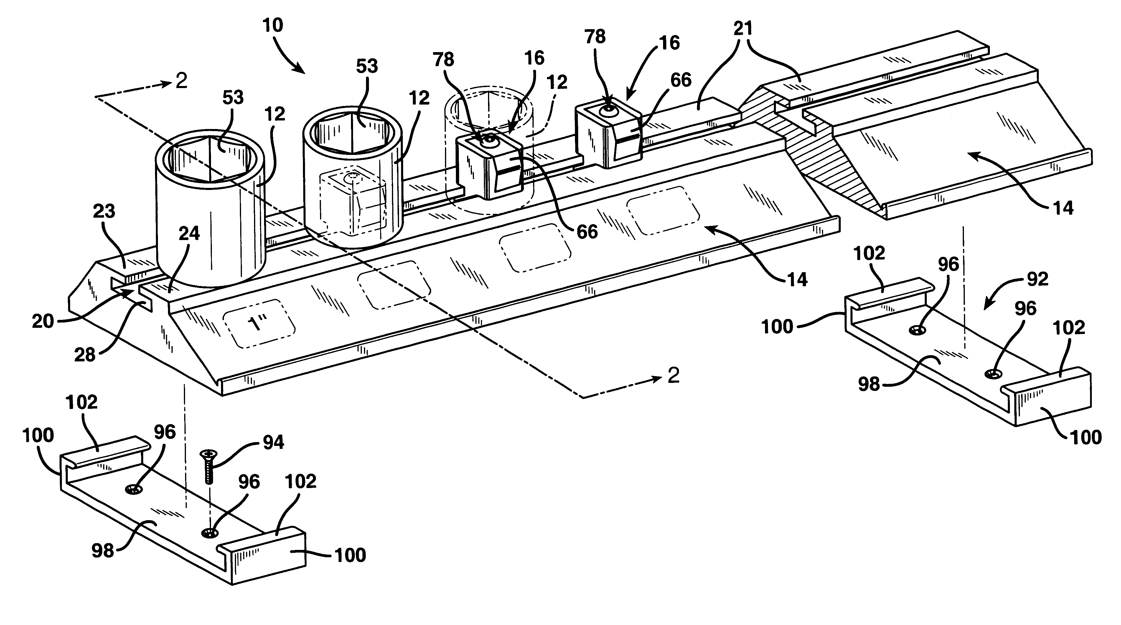
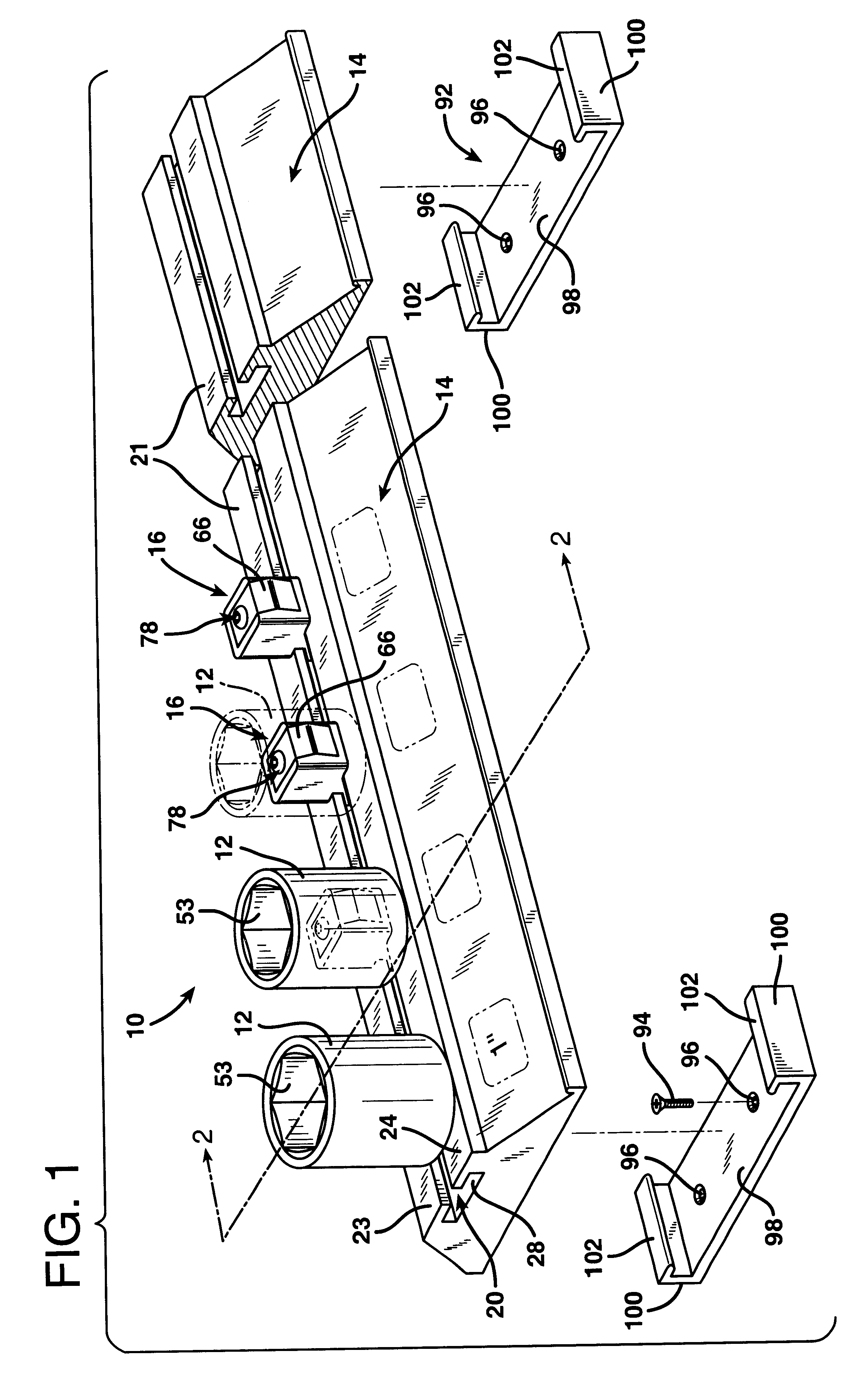
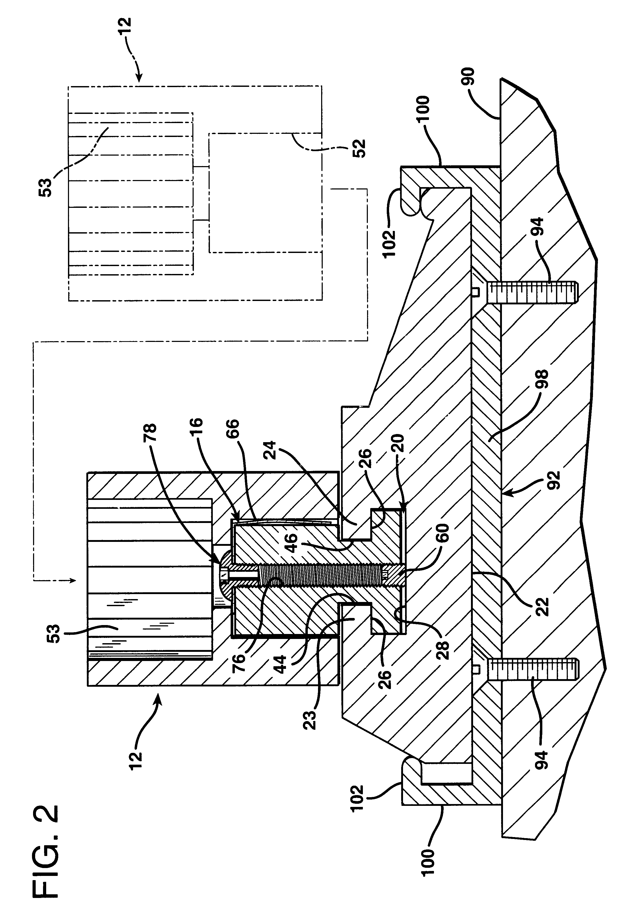
FIG. 1 illustrates a wrench socket rack 10 according to the invention for accommodating a plurality of wrench sockets 12, several of which are illustrated in FIG. 1. Each socket 12 has a square drive opening 52 at one end and a nut or bolt-head-engaging opening 53 at its opposite end, as best shown in the phantom portion of FIG. 2. The wrench socket rack 10 is comprised of an elongated support 14, which is formed as a mounting strip structure having a uniform cross section throughout its entire length, and a plurality of socket mounts or pegs 16, each one of which is of the type depicted in FIGS. 2 and 3.

As best illustrated in FIGS. 1-2, the elongated support 14 is formed with an elongated track 20, which has the cross-sectional configuration of an inverted "T". The mounting strip 14 has a flat bottom 22 and a flat top socket-mounting surface 21 located above the flat bottom 22. The track 20 is formed as a channel beneath the flat socket-mounting surface 21.

The elongated support 14 ...


PUM


Abstract

A wrench socket rack is formed of an elongated support defining a track with a pair of bearing surfaces overhanging the track from opposite sides. A plurality of socket pegs are provided. Each peg has a base with laterally projecting lugs that fit into the track. Each socket peg is sized to receive a wrench socket thereon. A bore with internal threads is defined from top to bottom in each of the socket pegs. A track-engaging clamp formed as a set screw that is threadably engaged in the socket peg at the bottom end of the bore. A hollow spring clamping screw is threadably engaged in the top end of the bore. The track-engaging set screw may be manipulated using a tool that is inserted through the cylindrical opening in the spring clamping screw.

Description

SPECIFICATIONBackground of the Invention1. Field of the InventionThe present invention relates to an improvement in an adjustable rack for receiving sockets of different sizes that are used with a socket wrench.2. Description of the Prior ArtOur prior U.S. application Ser. No. 09 / 398,717 filed Sep. 20, 1999 describes a wrench socket rack in which the positions of socket mounts are adjustable along the length of a track. That application is hereby incorporated herein by reference in its entirety. In this system an internally tapped threaded bore extends longitudinally throughout the length of the socket mount from the upper end of a socket peg to the bottom of the base of the socket mount. The base has laterally projecting lugs that extend beneath and face bearing ledges that overhang the track. Leaf springs are provided that are anchored to the top of each stud peg and which extend downwardly along one side of the stud. A single long screw that is threadably engaged in the internall...

Claims


Application Information

Patent Timeline
Patent Type & Authority Patents(United States)
IPC IPC(8): B25H3/00B25H3/06
CPCB25H3/06
Inventor RAMSEY, EDWARDVOVOS, CHRIS
Owner RAMSEY EDWARD
Why Eureka
Try Eureka